


SIEMENS Energy & Automation
10-21
SIMOREG DC Master Base Drive Panel Operating Instructions
PNU
Description
Value range
[Unit]
Steps
No. indices
Factory
setting
Type
See
Change
(Access /
Status)
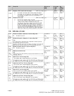
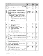
P092
(G200)
Delay times for field reversal
These times are used to control a reversing contactor for reversing the field
polarity on a 1-quadrant converter with field reversal.
i001: Delay time for the field reduction before opening of the current
field contactor
When field polarity reversal is initiated, the delay time set in
P092.i001 elapsed after reaching Ifield (K0265) < Ifield min
(P394) before the current field contactor is opened.
i002: Delay time before actuation of the new field contactor
[only SW 1.7 and later]
After opening the current field contactor the delay time set in
P092.i002 elapsed before the field contactor for the "new" field
direction is actuated (drop-out delay time of the contactor use is
usually longer then the pick-up delay time).
i003: Delay time for enabling the field firing pulses
[only SW 1.7 and later]
After actuation of the field contactor for the "new" field direction,
the delay time acc. to P092.i003 elapses before the field firing
pulses are enabled. This time must be longer than the pick-up
delay time of the contactor used.
i004: Delay time after the field build-up before armature enable
[only SW 1.7 and later]
After - directly following the field firing pulse enable - the actual
field current value Ifield in the "new" field direction has reached
the value Ifield (K0265) > Ifield set (K0268)*P398/100%, the
delay time acc. to P092.i004 elapses. Then the internal
(armature) "Operating enable of field reversal" is issued, i.e. the
Stopping of the drive in operating state
≥
o1.4 is canceled. This
delay time permits waiting of the end of overshooting of the
actual field current value and therefore overshooting of the EMF
of the DC machine straight after the field current has been built
up again, before the "armature operating enable" is issued. This
is intended to prevent armature overcurrents due to excessive
EMF during overshooting.
0.0 to 10.0
[s]
0.1s
Ind: 4
FS=
i001: 3.0
i002: 0.2
i003: 0.1
i004: 3.0
Type: O2
P052 = 3
P051 = 40
Online
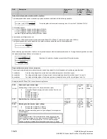
P093
Pick-up delay for line contactor
Pick-up of the line contactor is delayed in relation to "Switch on auxiliaries"
by the time delay set in this parameter.
0.0 to 120.0
[s]
0.1s
Ind: None
FS=0.0
Type: O2
P052 = 3
P051 = 40
Online
P094
Switch-off delay for auxiliaries
Switch-off of the auxiliaries is delayed in relation to dropout of the line
contactor by the time delay set in this parameter.
0.0 to 6500.0
[s]
0.1s
Ind: None
FS=0.0
Type: O2
P052 = 3
P051 = 40
Online
P095
Pick-up time for a contactor in the DC circuit
If the DC output (terminals 1C1 and 1D1) is switched through to the motor
via a contactor, and if this contactor is controlled by the "Relay for line
contactor" (terminals 109 and 110), then the gating pulses may not be
enabled until the contactor has safely picked up. For this purpose, it may be
necessary to parameterize an additional delay time for the pick-up
operation. The timer set in P095 commences during a pick-up operation
when the converter reaches operating state o5. If the timer has still not run
down by the time the converter exits state o4, then the converter dwells in
state o3.2 until the timer has finished.
During the time period set in P095, the "Main contactor checkback" signal
must also switch to "1" if this function is activated (see P691). Otherwise the
converter dwells in state o3.3 until the timer has finished and fault message
F004 is then output with fault value 6.
0.00 to 1.00
[s]
0.01s
Ind: None
FS=0.00
Type: O2
P052 = 3
P051 = 40
Online
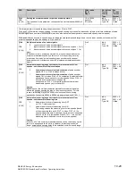
P096
After-running time for the device fan
[SW 1.6 and later]
After the drive has been shut down (operating state
≥
7.0 reached)
the device fan continues to run until the power section has cooled down.
With this parameter you can set the minimum duration for the after-running
time.
Note:
If the field current is not switched off after the drive is shut down (see P082),
the field current can prevent cooling of the power section. In this case, the
equipment blower is never switched off.
0.0 to 60.0
[min]
0.1min
Ind: None
FS=4.0
Type: O2
P052 = 3
P051 = 40
on-line
Содержание 6RA70 Series
Страница 9: ...1 4 Siemens Energy Automation SIMOREG DC Master Base Drive Panel Operating Instructions NOTES ...
Страница 23: ...3 12 Siemens Energy Automation SIMOREG DC Master Base Drive Panel Operating Instructions NOTES ...
Страница 25: ...4 2 Siemens Energy Automation SIMOREG DC Master Base Drive Panel Operating Instructions NOTES ...
Страница 31: ...5 6 Siemens Energy Automation SIMOREG DC Master Base Drive Panel Operating Instructions NOTES ...
Страница 45: ...6 14 Siemens Energy Automation SIMOREG DC Master Base Drive Panel Operating Instructions NOTES ...
Страница 60: ...Siemens Energy Automation 7 15 SIMOREG DC Master Base Drive Panel Operating Instructions NOTES ...
Страница 69: ...7 24 Siemens Energy Automation SIMOREG DC Master Base Drive Panel Operating Instructions NOTES ...
Страница 89: ...8 20 Siemens Energy Automation SIMOREG DC Master Base Drive Panel Operating Instructions NOTES ...
Страница 121: ...9 32 Siemens Energy Automation SIMOREG DC Master Base Drive Panel Operating Instructions NOTES ...
Страница 125: ...10 4 SIEMENS Energy Automation SIMOREG DC Master Base Drive Panel Operating Instructions NOTES ...
Страница 215: ...10 94 SIEMENS Energy Automation SIMOREG DC Master Base Drive Panel Operating Instructions NOTES ...