


Gamma
instabus
Technical product information
June 2014
Gamma arina touch sensor
Touch sensor, single
UP201/x2, without status LED and with orientation LED
5WG1 201-2DBx2
UP201/x3, with status LED and orientation LED
5WG1 201-2DBx3
Touch sensor, double
UP202/x2, without status LED and with orientation LED
5WG1 202-2DBx2
UP202/x3, with status LED and orientation LED
5WG1 202-2DBx3
Touch sensor, quadruple UP203/x2, without status LED and with orientation LED
5WG1 203-2DBx2
UP203/x3, with status LED and orientation LED
5WG1 203-2DBx3
UP203/x4, with status LED, orientation LED, scene controller and room temperature sensor
5WG1 203-2DBx4
UP203/x5, with status LED, orientation LED, scene controller, and IR receiver decoder
5WG1 203-2DBx5
UP 20x, UP 28x/3 and UP 28x/5
Technical product information
Siemens Building Technologies
Subject to change without further notice
Update: http://www.siemens.com/gamma
2.16.1.13/1
Product
Touch sensor, single
Touch sensor, double
Touch sensor, quadruple
without status LED and with ori-
entation LED
ivory white
5WG1 201-2DB12
5WG1 202-2DB12
5WG1 203-2DB12
champagne
5WG1 201-2DB32
5WG1 202-2DB32
5WG1 203-2DB32
with status LED and orientation
LED
ivory white
5WG1 201-2DB13
5WG1 202-2DB13
5WG1 203-2DB13
champagne
5WG1 201-2DB33
5WG1 202-2DB33
5WG1 203-2DB33
with status LED, orientation LED,
scene controller, and room
temperature sensor
ivory white
5WG1 203-2DB14
champagne
5WG1 203-2DB34
with status LED, orientation LED,
scene controller and IR receiver
decoder
ivory white
5WG1 203-2DB15
champagne
5WG1 203-2DB35
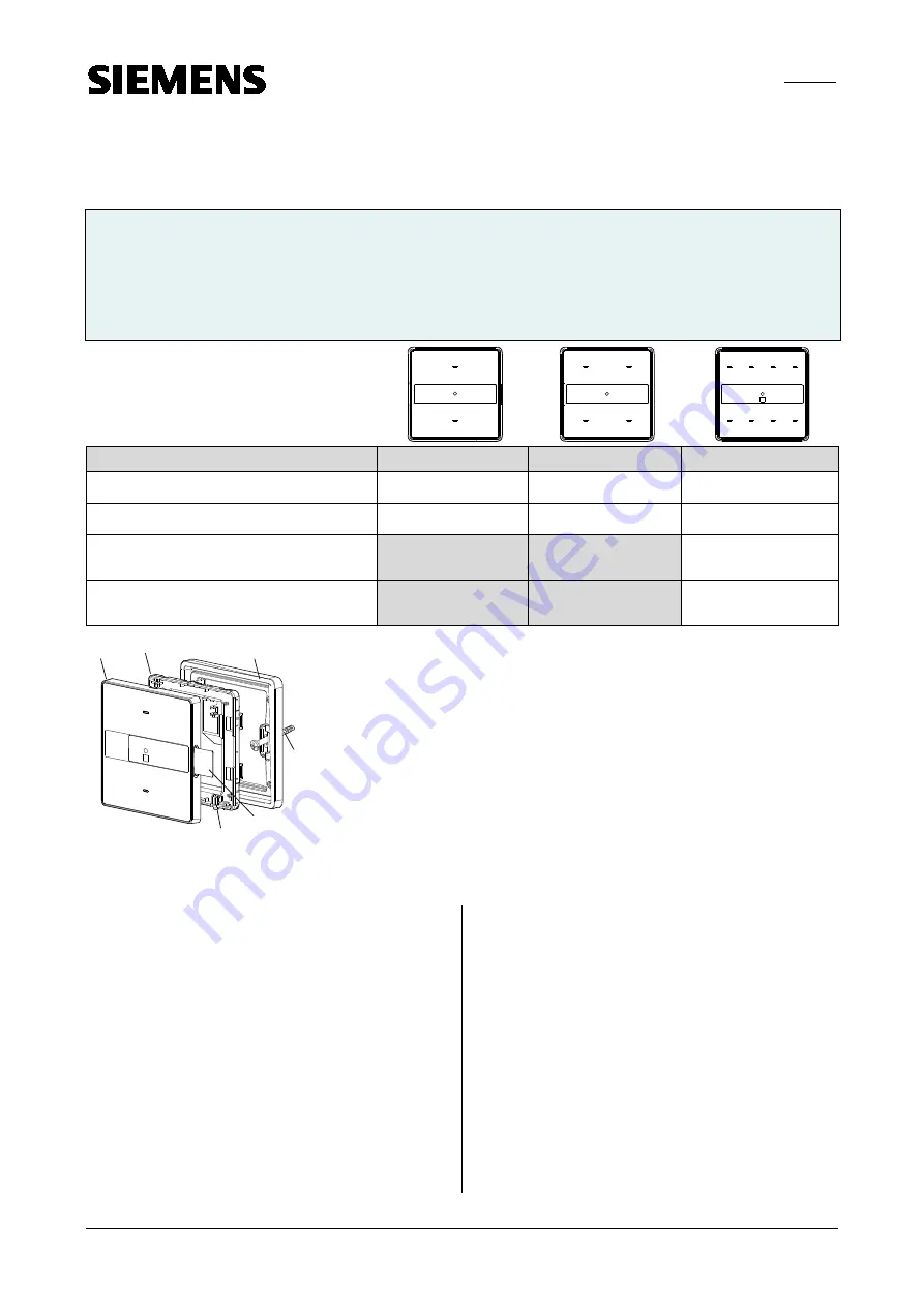
F1
F3
F4
F2
E6
F5
Figure 1: Mounting touch sensor arina
E6
Labelling field
F1
Mounting frame
F2
Mounting screws
F3
Back housing
F4
Front housing
F5
Programming button
Product and Applications Description
The touch sensors for the Gamma arina have one, two or
four vertically arranged pairs of sensitive touch areas. A
paper foil is placed in the middle between these sensitive
touch areas for labeling. The paper foil is replaceable
.
These types of touch sensors are available:
•
Touch sensor single, double and quadruple, with one
orientation LED, without status LED.
•
Touch sensor single, double and quadruple, with one
orientation LED and with one status LED per touch
area.
•
Touch sensor quadruple, with one orientation LED, one
status LED per touch area, scene controller, and room
temperature sensor.
•
Touch sensor quadruple, with one orientation LED, one
status LED per touch area and IR receiver-decoder.
The touch sensors are mounted together with the
mounting frame DELTA® arina onto a 86 mm x 86 mm
conduit box.
The mounting frame is not included and therefore have
to be ordered separately (see current catalog).


