


IV306E Rev. 004 Siel S.p.A.
Page 16 of 37 + 12 Tables, 14 F FR
Issued date: 2014-03-24
If the load is switched under mains, after 15 sec., conditions permitting (inverter OK, synchronism OK), the load is again
supplied from the inverter.
In the event of the "Forced" switch of an operating machine being operated (forced powering of load from mains), the
entire system switches to mains and remains there in all cases .
To prevent accidental operation, access to this command is only possible by opening the door of the UPS unit (featuring a
key).
The forced button must only be pressed when the machine is synchronised with the mains (green light on and synchronism
signal OK).
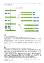
What has been said above can be summed up in the following reports:
If:
Nrid
is the redundancy number, whose values can be 0 and 1 (0= power parallel)
Ni
is the number of units that can supply the load with the inverter
NUPS is the number of UPSs making up the parallel
so the rule for defining load powering is the following:
if
Ni
≥
NUPS – Nrid
so the parallel powers the load from inverter.
If instead
Ni < NUPS – Nrid
the parallel powers the load from mains.
It should be noted that if NUPS is less than Nrid, Nrid is set equal to NUPS.
Equipment
Figure 2 shows the view of the UPS units with the front doors closed.
The opening of the front door, featuring a lock, gives access only to the input, output and bypass
disconnecting switches (if fitted); the UPS unit is supplied together with a key for accessing this
compartment. Fig. 3 shows the disconnecting switch compartment for the various types of UPS units.
The switches (Figures 1 and 3) are:
S1 Rectifier input disconnection switch
S2 UPS output disconnection switch
S3 Manual bypass (Not envisaged in case of UPS set for parallel)
S4 Reserve mains disconnection switch
To access the power compartments, open the front doors and open the board support door: this
operation can be performed using a simple screwdriver - not provided with the UPS unit.
The upper part of the equipment houses the control, measurement and signalling panel (shown in more
detail in Figure 4) and a LED mimic diagram (shown in greater detail in Figure 5).
When the front doors are closed, these are the only accessible components which provide useful
information and carry out all necessary checks.
Even with open doors with lock, the equipment still maintains an insulation standard of IP20, and no
live part is accessible.
Control, measurement and signalling panel.
The control, measurement and signalling panel on the front of the equipment (Figure 2) is shown
in detail in Figure 4 (referred to hereinafter as Signalling).
The signalling panel includes a liquid crystal display (LCD) with 80 characters, and control keys.
During normal UPS operation, signals appear showing the state of machine operation.
Some of these signals are repeated on the Functional diagram (Figure 5) where corresponding LEDs
light up to provide a quick overview of the operation of the different equipment subassemblies.


