


IV306E Rev. 004 Siel S.p.A.
Page 13 of 37 + 12 Tables, 14 F FR
Issued date: 2014-03-24
The Bypass manual disconnection switch (S3 in figure 1) is used to carry out maintenance on the
equipment without interrupting the supply of the load which keeps on being supplied by the reserve
mains (IN2).
In this case, the UPS can be completely switched off and disconnected from the installation through
the special S1, S2 and S4 disconnection switches, so that operations on the equipment can be carried
out in complete safety.
Obviously, when the load is fed by the manual By-pass, it is not protected against any mains outages.
Since the manual bypass circuit must supply the load as if there were no UPS, this circuit is not
protected and as such, suitable protection shall be provided in the plant. In the case of in-parallel
apparatus, the manual bypass must be external to the UPS as shown in Fig. 11.
No battery disconnect switch is envisaged because this is fitted inside the battery cabinet; if such a
cabinet cannot be fitted, a box must be installed near the batteries with disconnect switch and fuses or
automatic switch.
The UPS is provided with an electronic device (E.P.O), which can simultaneously block the Rectifier,
Inverter and Static switch operation, thus removing power from the load in case of emergency.
This device, though stopping operation of all UPS functions does not physically disconnect the
apparatus from the public mains and battery, consequently the switch-off command must be provided
by the system to the UPS together with other disconnections required by applicable regulations.
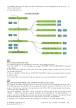
The integrity of the batteries is controlled periodically (normally every week) by provoking an
intentional small battery discharge and making sure this occurs properly. It should be noted that the
discharge is not determined by causing an intentional mains power break (which, in case of battery
inefficiency could prove dangerous for correct load supply), but rather by varying the voltage at which
the rectifier stabilises. This way, even in the case of totally faulty batteries, power continuity to the
load is in any case assured. Moreover, after a battery discharge (intentional or due to a blackout), the
time needed to recharge the battery is checked and if this is too long, an alarm is generated.
In the event of the UPS unit featuring a twelve-phase rectifier bridge, the current distortion reflected
towards the mains is reduced by 29% (total-controlled six-phase rectifier), to 7 or 11% depending on
the request.
This result can be obtained through specific magnetic components generating two triads of specially
phased voltages (30°) feeding two six-phase rectifying bridges.
The result is that the current absorbed by the network is the sum of the currents absorbed by the two
bridges; this way, the resulting current has a very low degree of distortion because its wave pattern
successfully approximates the sinusoidal pattern.
In all other respects, a UPS fitted with a twelve-phase bridge functions in exactly the same way as a
six-phase bridge.
When even lower input current distortions (
≤
5%) are required, the equipment may be fitted with a an
extra filter to correct the input current phase.
Moreover, UPSs with capacities from 500kVA to 1MVA can also be supplied in a version with a 24-
pulse rectifier bridge that, without the addition of extra filters, naturally guarantees a harmonic
distortion of the current lower than 5% (the technical specifications of these UPSs are given in
technical specification SP117 which integrates this document).
The version with the 24-pulse rectifier bridge may be supplied for UPSs with lower capacities on
request (for further information, please contact Siel SpA).


