


IV
3
0
6
E
e
S
P
1
3
3
E
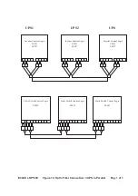
F
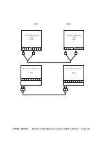
ig
u
re
1
4
:
O
p
ti
c
F
ib
e
r
C
o
n
n
e
c
ti
o
n
:
4
U
P
S
i
n
P
a
ra
ll
e
l
P
a
g
.
1
o
f
1
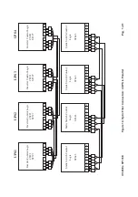
U
P
S
1
U
P
S
2
U
P
S
3
U
P
S
4
Inv
erter Control
L
o
g
ic
C
S
2
2
1
S
F
5
9
7
T
1
T
2
T
3
T
4
R
1
R
2
R
3
R
4
Inv
erter Control
L
o
g
ic
C
S
2
2
1
S
F
5
9
7
T
1
T
2
T
3
T
4
R
1
R
2
R
3
R
4
Inv
erter Control
L
o
g
ic
C
S
2
2
1
S
F
5
9
7
T
1
T
2
T
3
T
4
R
1
R
2
R
3
R
4
Inv
erter Control
L
o
g
ic
C
S
2
2
1
S
F
5
9
7
T
1
T
2
T
3
T
4
R
1
R
2
R
3
R
4
Static Switch Control
L
o
g
ic
S
F
6
4
3
T
1
R
1
T
2
R
2
T
3
R
3
T
4
R
4
T
5
R
5
Static Switch Control
L
o
g
ic
S
F
6
4
3
Static Switch Control
L
o
g
ic
S
F
6
4
3
Static Switch Control
L
o
g
ic
S
F
6
4
3
T
1
R
1
T
2
R
2
T
3
R
3
T
4
R
4
T
5
R
5
T
1
R
1
T
2
R
2
T
3
R
3
T
4
R
4
T
5
R
5
T
1
R
1
T
2
R
2
T
3
R
3
T
4
R
4
T
5
R
5


