


Chapter
6
Operating Instructions
Radio Frequency RFH620 Interrogator
44
©
SICK AG · Division Auto Ident · Germany · All rights reserved
8013105/0000/2009-05-12
Electrical installation
6.4.6
Wiring switching outputs
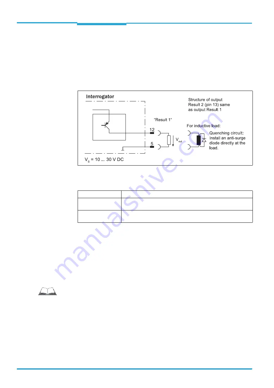
The two switching outputs "result 1" and "result 2" can be allocated various functions for
outputting the result status independent of each other. If the assigned result occurs in the
reading process, the corresponding switching output at the end of the reading pulse is live
for the selected impulse duration.
Important
The "result" LED is coupled with none of the two digital switching outputs "result 1" or
"result 2".
Fig. 6-6:
Possible wiring of "result 1" switching output on the 15-pole D-Sub-HD plug
Important
The ratings of the two switching outputs are identical.
Tab. 6-8:
Ratings for the switching outputs
Important
Capacitance loads
on the switching output affect the switching behaviour. Threshold is a
maximum capacitance of 100 nF. Exceeding this value can lead to unwanted pulsing beha-
viour of the output.
1. Connect switching outputs depending on application.
2. Wire the switching outputs with a load resistance to test the switching functions using
a high-resistance digital voltmeter.
Indication of incorrect voltages/switching statuses is avoided this way.
Switching behaviour
PNP switching against the distribution voltage U
V
Features
Short-circuit proof and temperature-protected,
not galvanically separated from U
V
Electrical values
0 V
≤
U
a
≤
U
V
Guaranteed: (U
V
−
1.5 V)
≤
U
a
≤
U
V
in I
a
≤
100 mA
Important
To wire the switching outputs using connection module CDB620 or CDM420, see the ope-
rating instructions "Connection Module CDB620" (no. 8012119, German/English edition)
and "Connection Module CDM420" (no. 8010004, German/English edition) respectively.