


Chapter
5
Operating Instructions
Radio Frequency RFH620 Interrogator
32
©
SICK AG · Division Auto Ident · Germany · All rights reserved
8013105/0000/2009-05-12
Installation
5.2.3
Mounting device
The interrogator is fixed using two blind hole taps (M6), which are located on each narrow
side of the device (see
chapter 10.2 Interrogator´s dimensional drawings RFH620.,
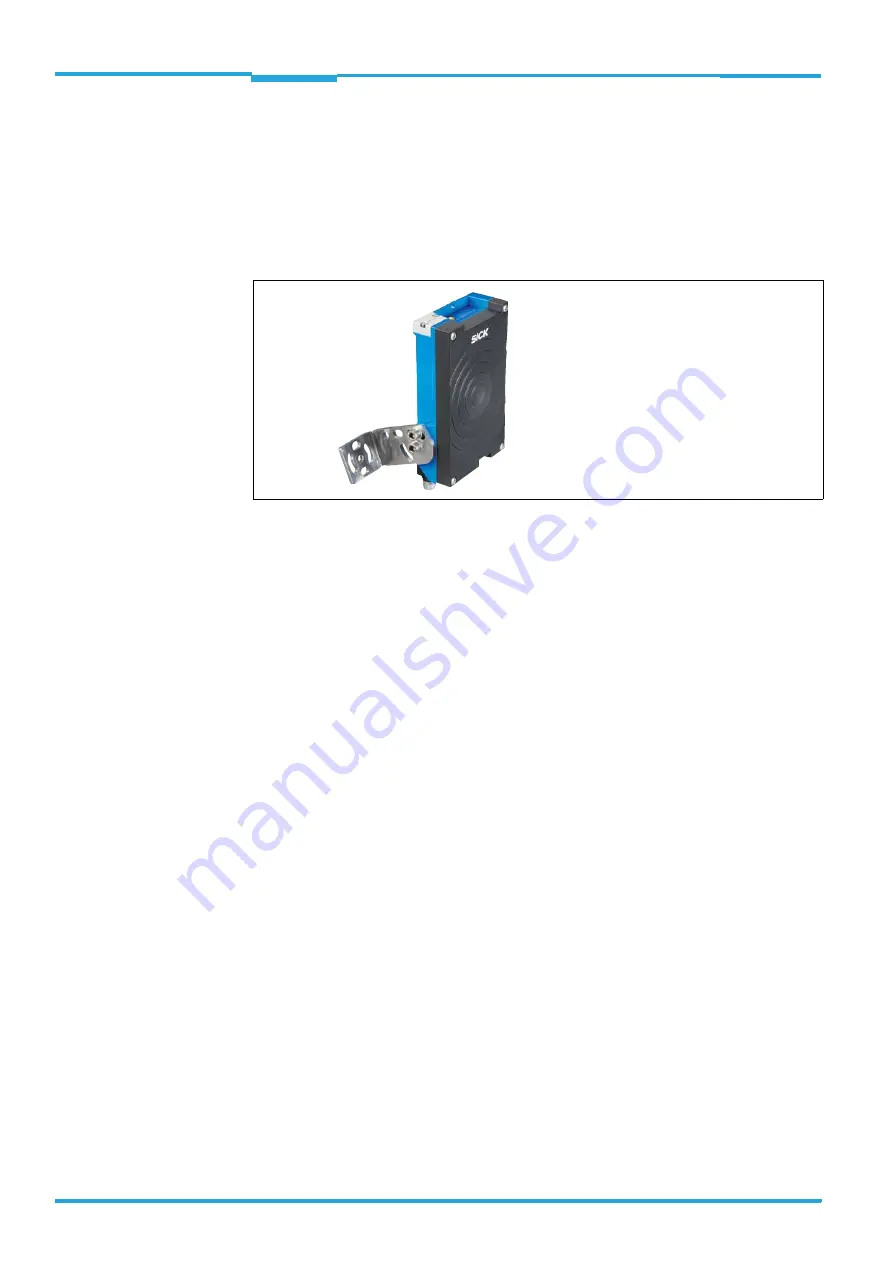
The interrogator is mounted using the SICK fastening bracket no. 2048551. The construc-
tion of the angle supports e. g. varied mounting options and the alignment of the interroga-
tor in two axes.
Fig. 5-1:
Example: Fixing the interrogator with bracket no. 2048551
Important
Always mount the bolts with washers.
When fixing the interrogator with bracket no. 2048551, pay attention to the following di-
mensions:
•
Max. thread reach of the blind hole taps: 6.5 mm (0.26 in)
•
Plate thickness of the fastening bracket: 4.0 mm (0.16 in)
•
Thickness of the washers: 1.6 mm (0.06 in)
•
Length of bolt M6x12: 12.0 mm (0.47 in)
The dimensioning of the SICK-holders shows
chapter 11.3 Dimensional drawing accesso-
Alternatively, the user can provide a holder.
The holder should meet the following requirements:
•
Stable mounting device
– Adjustable alignment of the interrogator in the x and y axis
– The mounting device must be able to bear the weight of the interrogator including
its connection cable (depending on the device version) without vibrating.
•
Two M6 bolts to fix the interrogator
– The screw length depends on the thickness of the mounting device
– Maximum thread reach in the interrogator 6.5 mm (0.26 in) from the housing sur-
face