background image

6

8015675/1EEU/2021-12| SICK

OP E R A T I N G   I N S T R U C T I O N S  | Flow-X

Subject to change without notice

1

ABOUT THIS DOCUMENT 

1

About this document

1.1

Function of this document

These Operating Instructions describe:

Device components

Installation

Commissioning

Operation

Maintenance work required for reliable operation

These Operating Instructions only cover standard applications which conform with the 

technical data specified. 
Additional information and assistance for special applications are available from your SICK 

representative. It is generally recommended to take advantage of qualified consulting 

services provided by SICK experts for your specific application.

1.2

Scope of application

These Operating Instructions are only applicable for the measuring device described in 

the product identification.

They are not applicable for other SICK measuring devices.

The standards referred to in these Operating Instructions are to be observed in the 

respective valid version.

1.3

Target groups

This Manual is intended for persons who install, operate and maintain the device.

1.4

Symbols and document conventions

1.4.1

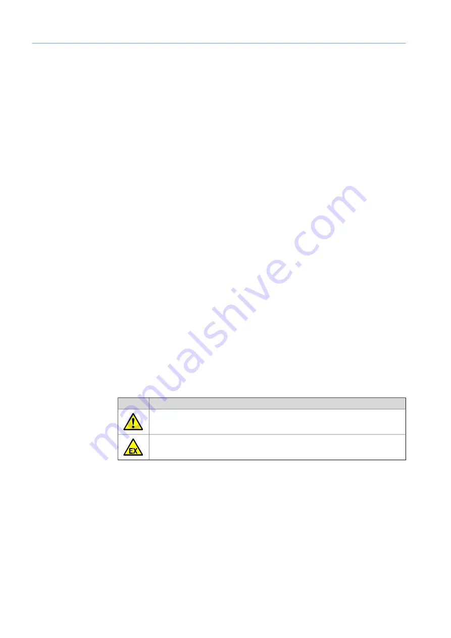
Warning symbols

Symbol

Significance

Hazard (general)

Hazard in potentially explosive atmospheres

Содержание Flow-X

Страница 1: ...MMMI MMMOPERATING INSTRUCTIONS OPE RATI NG INSTR UCTIO NS Flow X Gas Flow Computer Description installation operation Title Page ...

Страница 2: ...hts derived from the copyright shall be reserved for SICK Engineering GmbH Reproduction of this document or parts of this document is only permissible within the limits of the legal determination of Copyright Law Any modification shortening or translation of this document is prohibited without the express written permission of SICK Engineering GmbH The trademarks stated in this document are the pr...

Страница 3: ...Purpose of the device 8 2 2 2 Correct use 8 2 3 Responsibility of user 8 3 Product description 9 3 1 Flow X flow computer 9 3 2 Flow X M Module 9 3 3 Flow X enclosure 10 3 3 1 Flow X P 10 3 3 2 Flow X C 11 3 3 3 Flow X S 11 3 4 Flow X 11 3 5 Type plate 12 3 6 Multi module operation 12 3 7 Configuration protection 12 3 7 1 Parameter locking switch 12 3 7 2 Metrological seal 12 3 7 3 Passwords 12 3 ...

Страница 4: ... serial communication 27 4 3 8 Ethernet 27 5 Commissioning 28 5 1 Device settings 28 5 2 Connecting devices with HART protocol 29 5 2 1 Pressure sensor 29 5 2 2 Temperature transmitter 29 5 3 Connecting analog devices 30 5 3 1 Pressure transmitter 30 5 3 2 Temperature transmitter 31 5 4 Device configuration and connection check 31 5 4 1 FLOWSIC600 XT 31 5 4 2 Pressure transmitter 33 5 4 3 Temperat...

Страница 5: ...ormities 41 7 1 1 CE certificate 41 7 1 2 Standards compatibility and type approvals 41 7 2 General specifications 41 7 3 Flow X M I O specifications 43 7 3 1 I O signal specifications 43 7 3 2 Specifications for flow calculation 44 7 3 3 Supported devices 45 7 4 Power consumption 45 7 5 Weight 45 7 6 Dimensions 46 7 7 Wiring example 52 ...

Страница 6: ...from your SICK representative It is generally recommended to take advantage of qualified consulting services provided by SICK experts for your specific application 1 2 Scope of application These Operating Instructions are only applicable for the measuring device described in the product identification They are not applicable for other SICK measuring devices The standards referred to in these Opera...

Страница 7: ...standard IP technology in its products The focus here is on the availability of the products and their properties SICK AG always assumes that the customer is responsible for the integrity and confidentiality of data and rights involved in connection with using the products In all cases the customer is responsible for the implementation of safety measures suitable for the respective situation e g n...

Страница 8: ...ters It may only be used as specified by the manufacturer 2 2 2 Correct use The device may only be used as described in the Operating Instructions Pay special attention that The usage of the technical data corresponds to the specifications on allowable use as well as assembly connection ambient and operating conditions see the order documents device pass type plates and documentation delivered wit...

Страница 9: ...g transmitter input high accuracy Input types 4 20 mA 0 20 mA 0 5 V 1 5 V Accuracy mA inputs 0 002 FS at 21 C 0 008 at full ambient range of 0 60 C long term stability 0 01 year resolution 24 bit Analog inputs share a common floating ground in relation to all other electronics 4 wire PRT inputs 2 Resolution 0 02 C for 100 Ohm input Error depending on range 0 50 C Error 0 05 C or better 220 220 C E...

Страница 10: ...24 mA Pulse outputs 4 2 Open collector 0 01 to 500 Hz Inputs of the sphere detector 4 2 Supports 1 2 and 4 detector configuration mode Resolution 100 ns 10 MHz Prover bus outputs 1 2 Meter pulse output for remote flow computers Resolution 100 ns 1 MHz Frequency outputs 4 2 Frequency outputs for emulation of flow meter signals Maximum frequency 10 KHz accuracy 0 1 Serial 2 RS485 RS 232 serial input...

Страница 11: ...thernet interfaces Fig 3 Flow X C enclosure with internally installed Flow X module 3 3 3 Flow X S The Flow X S enclosure is a single module enclosure with DIN rail enclosure with direct screw terminals for the field connections and is used as single measuring section Fig 4 Flow X S enclosure with a Flow X module 3 4 Flow X The Flow X T is a 7 inch color touchscreen that can be installed in an ins...

Страница 12: ...Ethernet interface 3 7 Configuration protection 3 7 1 Parameter locking switch Each individual Flow X module has a mechanical parameter locking switch which prevents the change of crucial parameters within the program Fig 7 Parameter locking switch 3 7 2 Metrological seal All Flow X enclosures have the option of sealing the parameter locking switch of the individual Flow X modules with a seal On a...

Страница 13: ...rms Windows 32 bit x86 WinCE5 ARM WinCE6 x86 A single touch panel can be used for several Flow X flow computers providing a cost effective user interface SICK offers a 7 inch touch panel PC version designed for cabinet installation 3 8 3 Flow X module LCD display Each Flow X module has an LCD display The display provides access to local Flow X module data and when the module is installed in a Flow...

Страница 14: ...e Opera etc The web browser offers the same features as the main user interface plus an Explorer Tree for easy navigation It also serves to download reports and historical data 3 8 5 Touchscreen user interface layout Flow X flow computer user interfaces have the following layout and buttons Fig 9 Main menu of the Flow X flow computers 1 Go to Main menu 2 Up one menu level 3 One step backward 4 One...

Страница 15: ...flow computer Live Values Flow Rates Flow Meter Configuration System IO Communication Smart Meter Run COM Ports Diagnostics Configuration FLOWSIC600 Flow Meter Pressure Transmitter Temperature Transmitter Pressure Temperature COM1 Analog Inputs Analog Inputs FLOWSIC600 Communication FLOWSIC600 Path Data Pressure Communication Temperature Communication Main menu Submenu Submenu ...

Страница 16: ... with a host computer Web services are available for the following data and actions Alarm states and acknowledgment General device information Menu structure of the display Text translations to foreign languages Event logs Historical data archives List of archived reports Reading out individual reports Reading and writing data values Units and item lists A detailed description of the Flow X XML in...

Страница 17: ...A5 AGA8 Parts 1 and 2 AGA10 AGA NX19 SGERG 88 GERG 2008 GOST 30319 2 GPA 2172 ISO 6976 all editions GSSSD MR113 Wet gas De Leeuw Reader Harris Flow ISO 5167 1 2 3 and 4 all editions ISO TR15377 AGA3 AGA7 AGA9 AGA11 V cone 4 1 3 Number of modules One module typically represents a metering run Station totals can be calculated in any module in the same enclosure including the Flow X P panel display m...

Страница 18: ...Each Flow X module can use the data from other modules as if it exists in its own data space SICK Flow X P has two dedicated Ethernet switches for this purpose Alternatively it is possible to set up a Modbus TCP IP link using Ethernet to exchange data between the modules 4 1 6 Display requirements The Flow X P and Flow X C touchscreen supports effective and user friendly data display and navigatio...

Страница 19: ... P the mounting bracket is designed to allow unobstructed access to the installed Flow X modules The mounting bracket is attached to the back of the instrument panel in which the Flow X P or Flow X C flow computer is to be installed The respective flow computer is inserted at the front of the instrument panel and connected to the mounting bracket with a screw Fig 11 Flow X P mounting bracket and s...

Страница 20: ...e fully configurable using the software No DIP switches or jumpers need to be set inside Furthermore there are no user replaceable fuses or other components inside Opening a module voids all warranty claims For the sake of simplicity the details of the plug in connections are described first The loop diagrams and additional connection drawings then follow WARNING The device may only then be connec...

Страница 21: ... only required for intrinsically safe installation Volume flow a c Ex i Ex i Ex i p T Specification Remark Cable type Twisted pair shielded Cable impedance approx 100 150 W Low cable capacitance 100 pF m Connect shielding at other end to ground terminal Min max cross section 2 x 0 5 1 mm2 2 x 20 18 AWG Maximum cable length 300 m at 0 5 mm 500 m at 0 75 mm Do not connect unused conductor pairs and ...

Страница 22: ...k The Flow XP modules are used in multi module operation Fig 15 Connection links position Connection type Flow X S Flow X P Flow X C RJ45 plug 2x LAN1 and LAN2 2x LAN1 and LAN2 2x LAN1 and LAN2 9 Pin D sub connector serial interface 1x RS 232 COM1 x 2x RS 232 or RS485 COM2 and COM3 1RS 232 COM3 x or 1RS 485 COM3 37 Pin D sub sockets I O and serial ports 8x X1A X4A and X1B to X4B 2x X1A and X1B Scr...

Страница 23: ...d to one the terminal s 24 V DC Primary and one of the 0 V DC terminal s The optional secondary power supply must be connected to one the terminal s 24 V DC Secondary and one of the 0 V DC terminal s Fig 16 Flow X power terminal block Flow X P left and Flow X S or Flow X C right WARNING The device may only then be connected to the power supply when ALL of the other desired lines and plugs are conn...

Страница 24: ...ected to the Analog 2 HART 2 port of the Flow X flow computer module used Fig 17 Field connection using the FLOWSIC600 XT as example Fig 18 General transmitter connection with internal 24 V supply WARNING Before connecting the analog signals to the flow computer make sure the analog input values voltage current and ranges are configured correctly Incorrect configuration can cause damage to the inp...

Страница 25: ...f the corresponding measuring section according to the following Figures when several measuring sections are installed D sub A D sub B 1 2 3 4 1 Measuring section 1 2 Measuring section 2 3 Measuring section 3 4 Measuring section 4 1 D sub A D sub B Connected device Terminal ID Plug connection Pin Serial Com Port 1 Gas flow meter TRx X1A 1 TRx X1A 2 Analog HART Input 1 Pressure transmitter X1A 32 X...

Страница 26: ... Flow X S Connected device Terminal ID Plug connection Pin Serial Com Port 1 Gas flow meter TRx X1B 32 TRx X1B 33 Analog HART Input 1 Pressure transmitter X1B 11 X1B 12 Analog HART Input 2 Temperature transmitter X1B 13 X1B 14 24 V out Pressure or temperature transmitter X1A 1 0 V common X1A 2 X1A 4 Table 7 37 pin connection port Flow X S ...

Страница 27: ...e not in a multi module configuration the Ethernet ports can be used to communicate with the flow module This also applies when the flow module is the first flow computer in a multi module configuration First means the first in the software program this does not necessarily correspond to the physical position within the rack Pin COM1 RS 232 only COM2 COM3 RS 232 RS485 2 wire RS485 4 wire COM3 Flow...

Страница 28: ...on is the same for all variants A login is required for the Flow X flow computer touchscreen or integrated Web server settings 1 Touch or click Login Fig 22 Login menu 2 Enter the user name and corresponding password 3 Confirm Login When making changes using the module screen it is necessary to log in with your pin in the Login menu Fig 23 Menu Login Flow X module LCD display Login User name Passw...

Страница 29: ...ressure 3 Go to menu item IO Diagnostics Analog inputs The value of Analog input 1 input value must be 4 mA Fig 25 IO Diagnostics Analog inputs pressure sensor 5 2 2 Temperature transmitter 1 Go to menu item Configuration Run Pressure 2 Set the Meter pressure input type to HART 3 Go to menu item IO Diagnostics Analog inputs The value of Analog input 2 input value must be 4 mA Fig 26 IO Diagnostics...

Страница 30: ...ut value must be between 4 mA and 20 mA If this is not the case the function of the transmitter must be checked and whether there are any error values defined by the device Adjusting the scale in the flow computer to the working range of the transmitter 1 Go to menu item IO Diagnostics Analog inputs 2 Set the value for Analog input 1 full scale to the maximum value of the measuring range of the pr...

Страница 31: ...r to the working range of the transmitter 1 Go to menu item IO Diagnostics Analog inputs 2 Set the value for Analog input 2 full scale to the maximum value of the measuring range of the temperature transmitter 3 Set the value for Analog input 2 zero scale to the minimum value of the measuring range of the temperature transmitter 5 4 Device configuration and connection check 5 4 1 FLOWSIC600 XT Che...

Страница 32: ...anging the protocol type is only possible via the FLOWgate software for the FLOWSIC600 XT or via the Flow Xpress software for the flow computer See Section Configuration with FLOWgateTM for further information 5 In menu item Flow rates check that the Flow X flow computer receives data from the gas flow meter used under Gross volume flow rate The data must match the flow rate displayed by the gas m...

Страница 33: ...n Status is set to OK the correct device ID is already set in the flow computer Fig 32 Menu item Communication Pressure Hart Pressure Communication Changing the device ID 1 Go to menu item Communication Pressure Hart Pressure Communication 2 Change the HART slave ID to the device ID set in the device 3 Check the communication status again 4 Go to menu item Live Values Run 5 Check that the flow com...

Страница 34: ...ation Note The reference value of the ambient pressure is 1 01325 bar a Fig 34 Menu item Configuration Run Pressure 5 4 3 Temperature transmitter Checking the communication status 1 Go to menu item Communication Temperature Transmitter Temperature Communication 2 Check the Communication status When the Communication Status is set to OK the correct device ID is already set in the flow computer Chan...

Страница 35: ...etrological settings The following settings are required by the MID Measuring Instruments Directive Go to menu item Display Metrological Accountable alarm This display is only visible when MID compliance Configuration Overall setup Overall setup is activated Setting Security level Description Qmin 1000 Low range value lowest permissible flow rate of the gas flow meter The corresponding alarm is tr...

Страница 36: ... gas flow meter communication FLOWgate In the following the FLOWgate software is mainly used to configure the FLOWSIC600 XT gas flow meter FLOWgate graphical user interface Fig 36 FLOWgate graphical user interface Note For more detailed information on the software and its use refer to the FLOWgate Section of the FLOWSIC600 XT Operating Instructions ...

Страница 37: ...o gas flow Fig 37 Menu item Flow Meter Smart meter 2 Start the FLOWgate software on the computer connected to the gas flow meter and connect to the connected gas flow meter 3 Select SERVICE and I O CHECK in the menu tree on the right side 4 Select pulse outputs FO 0 FO 1 and switch to Configuration mode 5 Enter any value for Test frequency or Test flow rate and move the slide switch to Run Fig 38 ...

Страница 38: ...ation with FLOWgate 1 Start the FLOWgate software on the computer connected to the gas flow meter 2 In the menu tree on the right side select PARAMETER MODIFICATION and I O CONFIGURATION 3 Select the desired interface 4 Now select Protocol Baudrate Protocol Bits etc Fig 40 Changing the interface 5 Configuration mode must be activated to make changes Finally the changes must be confirmed with the W...

Страница 39: ...Flow X flow computer webserver or module screen Login is required to change settings To do this proceed as explained in the Device settings Section 1 Go to menu item System Modules Module 1 COM Ports COM1 2 Change the baud rate data bits parity and stop bits to the values set in FLOWgateTM Fig 41 Menu item System Modules Module 1 COM Ports COM1 ...

Страница 40: ...er must be changed Changing the transmitter measuring mode 1 Go to menu item Configuration Run Pressure 2 Change the value for Meter pressure input units to absolute or gauge depending on the transmitter configuration If anything is unclear check the transmitter configuration Note The reference value of ambient pressure is 1 01325 bar a 6 4 Verifying the analog temperature transmitter If the analo...

Страница 41: ...tions EN 61000 6 4 EN12405 1 A2 AGA 10 AGA 8 Type approval for commercial or custody transfer has been granted by the relevant authorities e g MID approval NMI Nederlands Meetinstituut T10548 Flow X P X M X S X R T11449 Flow X C 7 2 General specifications Item Type Description Quantity Temperature Operating hours Operating temperature range Flow X S 5 55 C 41 131 F Flow X P 25 55 C 13 131 F Flow X...

Страница 42: ... T ING INST R U CT IO NS Flow X Subject to change without notice 7 APPENDIX Further specifications Item Specification MTBF At least 10 years EMC EN 61326 1997 Industrial location EN 55011 Enclosure EN 60950 Table 12 Further specifications ...

Страница 43: ...speed USM counter input pulse counting Trigger level0 5 V Max level30 V Frequency range 0 5 kHz 4 x dual pulse or 0 10 kHz 4 x single pulse Compliant with ISO6551 IP252 and API 5 5 True Level A implementation Digital input 16 1 High impedance Digital status input or test inputs Update cycle 0 5 ms for 2 inputs for others 250 ms max Digital output 16 1 Open Collector Update cycle for relays etc 0 5...

Страница 44: ...16 Certified flow calculations Standard flow calculations Recalculation of batch and period counter factor BS W density etc Unlimited number of period and batch totals and weighted averages of flow and time Any type of period is possible Maintenance counters are supported Calibration curve up to an unlimited number of points linear and polynomial Support for test system Unidirectional bidirectiona...

Страница 45: ...c flow meters Product family SICK FLOWSIC All major gas chromatographs All major gas chromatographs ABB Daniel Instromet Siemens All gas chromatographs that support Modbus Table 18 Standard supported devices Device Nominal value Peak value at power on Flow X C 0 6 A 1 0 A Flow X P 0 4 A 0 8 A Flow X 0 4 A 0 8 A Table 19 Power consumption at 24 V DC exclusive supply of external transmitter loops Pr...

Страница 46: ...46 8015675 1EEU 2021 12 SICK OP ER A T ING INST R U CT IO NS Flow X Subject to change without notice 7 APPENDIX 7 6 Dimensions Fig 42 Flow X P dimensions Front view Rear view Side view ...

Страница 47: ...47 8015675 1EEU 2021 12 SICK O P ER A TI NG INST R UC TI O NS Flow X Subject to change without notice APPENDIX 7 Dimension Flow X C Front view Rear view ...

Страница 48: ...15675 1EEU 2021 12 SICK OP ER A T ING INST R U CT IO NS Flow X Subject to change without notice 7 APPENDIX Fig 43 Flow X P wall bracket dimensions Fig 44 Flow X C wall bracket dimensions Side view Side view ...

Страница 49: ...49 8015675 1EEU 2021 12 SICK O P ER A TI NG INST R UC TI O NS Flow X Subject to change without notice APPENDIX 7 Fig 45 Flow X T dimensions Fig 46 Flow X S horizontal dimensions ...

Страница 50: ...50 8015675 1EEU 2021 12 SICK OP ER A T ING INST R U CT IO NS Flow X Subject to change without notice 7 APPENDIX Fig 47 Flow X S vertical dimensions Fig 48 Flow X S wall mounted dimensions ...

Страница 51: ...51 8015675 1EEU 2021 12 SICK O P ER A TI NG INST R UC TI O NS Flow X Subject to change without notice APPENDIX 7 Fig 49 Flow X S wall mounted dimensions side view ...

Страница 52: ...see Compliance CSA 1298901 Certificate of Conformity TÜV 01 ATEX 1766 X resp Certificate of Flowsic 600 Certificates Network SCADA 2x2x0 5 mm Li2YCYv TP 2x2x0 5 mm Li2YCYv TP 2x2x0 5 mm Li2YCYv TP 2x1 5 mm NYY O the devices to fail Flow computer Flow X 2x1 5 mm NYY O Flow X P1 X1A ETH 1 ETH 2 24 VDC Power supply 0V 0V 24V TRx TRx AI1 AI1 AI2 AI2 Pressure Temperature internally linked 5 6 1 2 5 9 1...

Страница 53: ...icates National regulation must be observed in EU in accordance with EN 60079 14 in North America in accordance with NEC and CEC see Intrinsic safety installation Network SCADA Ex safety barrier Power Supply 24 VDC Intrinsic safety circuits Non Intrinsic safety circuits Screen Screen Screen Screen Screen Screen 2x2x0 5 mm Li2YCYv TP 2x2x0 5 mm Li2YCYv TP 2x2x0 5 mm Li2YCYv TP 2x2x0 5 mm Li2YCYv TP...

Страница 54: ...P Italy 3KRQH 0DLO LQIR VLFN LW Japan 3KRQH 0DLO VXSSRUW VLFN MS Malaysia 3KRQH 0DLO HQTXLU P VLFN FRP Mexico 3KRQH E Mail mexico sick com Netherlands 3KRQH 0DLO LQIR VLFN QO New Zealand 3KRQH WROOIUHH E Mail sales sick co nz Norway 3KRQH E Mail sick sick no Poland 3KRQH 0DLO LQIR VLFN SO Romania 3KRQH 0DLO RIILFH VLFN UR Russia 3KRQH 0DLO LQIR VLFN UX Singapore 3KRQH 0DLO VDOHV JVJ VLFN FRP Slova...

Отзывы: