


20
8015675/1EEU/2021-12| SICK
OP E R A T I N G I N S T R U C T I O N S | Flow-X
Subject to change without notice
4
INSTALLATION
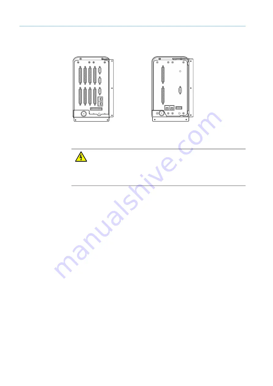
All plug connectors for power, field wiring and communication are located on the rear of the
Flow-X/P or Flow-X/C.
Fig. 13: Flow-X/P (left) and Flow-X/C (right) , rear view (installed)
4.3
Electrical installation
4.3.1
Introduction
This Section contains information for electrical installation, including field wiring,
communications, power supply and grounding. Since all models use the same Flow-X
module, the connection diagrams in this Section apply to all models.
The Flow-X modules are fully configurable using the software. No DIP switches or jumpers
need to be set inside. Furthermore, there are no user-replaceable fuses or other
components inside. Opening a module voids all warranty claims.
For the sake of simplicity, the details of the plug-in connections are described first. The loop
diagrams and additional connection drawings then follow.
WARNING:
The device may only then be connected to the power supply when ALL of the other
desired lines and plugs are connected to the device.
A plug or cable may only be disconnected from the device when the voltage supply to
the device has been disconnected beforehand.
Connecting plugs or cables while the device is in operation can cause irreparable
damage to the electronics. Corresponding defects are excluded from a warranty claim.


