


24
8015675/1EEU/2021-12| SICK
OP E R A T I N G I N S T R U C T I O N S | Flow-X
Subject to change without notice
4
INSTALLATION
4.3.6
Field connections
The FLOWSIC600-XT is connected to the serial COM Port 1 of the module used via the
corresponding RS485 interface. Terminal 81/82 is used for this purpose on the
FLOWSIC600. For connection with a 2-wire RS-485 connection, it is sufficient to use the
Tx+ and Tx terminals. Alternatively, an Ethernet connection can be used to connect the
FLOWSIC600-XT and flow computer.
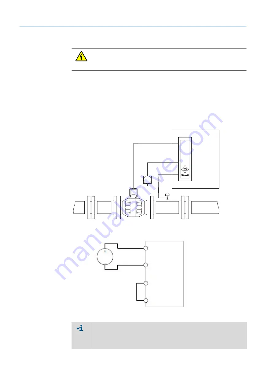
The pressure transmitter is connected to the Analog 1/HART 1 port, while the temperature
transmitter is connected to the Analog 2/HART 2 port of the Flow-X flow computer module
used.
Fig. 17: Field connection using the FLOWSIC600-XT as example
Fig. 18: General transmitter connection with internal 24 V supply
WARNING:
Before connecting the analog signals to the flow computer, make sure the analog input
values (voltage/current) and ranges are configured correctly. Incorrect configuration
can cause damage to the inputs.
p
T
Module 1
RS485
Analog 2
Analog 1
Flow-X
flow computer
24 V out
Analog input
signal
0 V
Analog output
common
(0) 4 - 20 mA
transm.
Both transmitters can receive their 24 V supply voltage via internal supply from the
Flow-X flow computer and can be connected accordingly. This may require additional
cables.
An external supply is also possible, the correct connection is described in
→ Technical
Information §3.4.10
.


