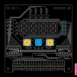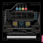
CIRCUIT
U5
C1
74HC595
U6
74HC595
C2
R19
LE
D
-1
LE
D
-2
LE
D
-3
LE
D
-4
DIG-4
DIG-3
DIG-2
DIG-1
SEG
-G
SEG-F
SEG
-A
SEG-B
SEG-DP
SEG
-C
SEG-D
SEG-E
OE
SER
LA
T
CLK
Q
h’
+5V
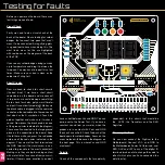
Circuit - Shift Registers
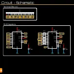
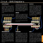
74HC595 Shift Register
The 74HC595 shift register is a Serial In,
Parallel Out (SIPO) shift register. Data in
electronics is stored as 1’s and 0’s which
represents a switch in an on or off state. One
of these switches is a bit, and 8 bits make
a byte. In a SIPO Shift Register data is sent
1 bit at a time into the 8 bit register, these
can then be output all at the same time in
parallel.
Bits of data are sent from the microcontroller
using the shift register’s Serial, Clock and
Latch pins. First, the Latch pin is turned on
(“sent high”), this tells the shift register that
data is going to be sent via the Serial pin. The
bits are sent to the Serial pin one at a time.
Whenever the Clock pin is sent high, the cur-
rent state of the Serial pin (on or off, 1 or 0) is
pushed through the shift register. After all 8
bits are shifted, the Latch pin should go low
again, this sends the bits to the outputs. See
the component index for a diagram.
Output pins
The outputs can comfortably output 6mA
(milliamp). If they exceed this, Vcc (power
supply voltage) will likely drop considerably.
To keep current output low, we’ve used high
value resistors with the LEDs, and Transistor
switches for the display’s common anodes.
Note: In v1 of the PCB there is an error in the silkscreen.
There is an extra line coming straight up from pin 15 of U5.
Please ignore this line.
Output Enable
Output Enable (OE) is used to instantly turn
all outputs off, or on. To enable the outputs,
the OE pin must be pulled low. To turn them
all off, OE must be pulled high. There is a
pull-down resistor connected to OE, which
means it is on, until it is pulled high by the
microcontroller. If connected to a PWM en-
abled microcontroller pin, OE can be used
to dim the display. Use analogWrite(0); to
turn the display on, analogWrite(255); to
turn them off. You can use any number in
between to dim the display.
5V VCC
The 74HC595 can run on 2 to 6 Volts. So
our 5V VCC works fine. The problem with
using the 595s is their recommended output
of 6mA per pin. This isn’t enough to drive
several LEDs, so we use the output of the
595 to activate a Transistor switch, which in
turn lets more current flow safely outside the
chip. There are several better shift registers
out there, but these teach us some valuable
lessons about the limits of components and
ways to get around them.
Qh’ Serial Output
Several 595 Shift Registers can be chained
together using the same 3 or 4 data pins
of a microcontroller. Bits are sent from
the microcontroller into the board’s SER
input, then to the SER pin of the first shift
register, out the Qh’ pin of the first, into the
SER pin of the second. The data can then
be chained to another shift register (on the
RGB Matrix for example) by connecting the
output Qh’ terminal (from the second regis-
ter) to the SER terminal of the next board.
Bypass Capacitors C1, C2
These are decoupling capacitors. Their func-
tion is to smooth out any noise (spikes or
drops in voltage) due to other components
affecting the power supply to the Integrat-
ed Circuit. It ‘decouples’ the chip from the
noise created by other parts of the circuit.
It does this by holding an amount of charge
and releasing it when the voltage drops, to
compensate. It is placed between power and
ground, as close to the IC’s (chip’s) VCC pin
as possible.
1
16
2
15
3
14
4
13
5
12
6
11
7
10
8
9


