20
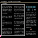
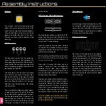
Switches
The switches will fit into their holes quite
tightly. If they don’t pop in flat to the PCB,
check that the legs are all aligned properly.
They should hold on their own, so flip the
board and solder the pins to the pads.
The pins are short so they shouldn’t need
trimming.
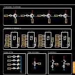
PNP Transistors
The transistors can be tricky to solder be-
cause the legs are so close together. We
have spaced the pads out a little to make it
easier. Notice the semi-circular shape of the
transistor looking at the top. Match this with
the footprint on the PCB.
The outer legs of the transistor will spread
out a little as you insert it into the holes.
Don’t push it too far as the legs will spread
too much and crack the black casing of the
transistor. Stop when there’s a 2-3mm gap.
Add sticky tack to hold in place, flip, solder,
snip and re-flow.
If you accidentally bridge two pads togeth-
er, clean your iron, re-tin the tip, then drag
the tip through the gap between the pads.
This should separate them. If it doesn’t, re-
peat the process. If your tip isn’t clean, the
solder won’t stick to the tip when you drag
it through, so make sure that tip is clean
and re-tinned.
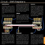
DIP16 Socket / 595 Shift Registers
We are going to solder a socket to the PCB
rather than the chip itself. We do this to
avoid heating up the IC and to enable us to
swap it out if it stops working.
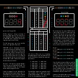
Insert the sockets into the areas marked
U1 and U2. Pay attention to the semi-circle
indicator and match the one on the socket
with the one on the board.
Note: an error on v1 of the board means the semi-circles
have accidentally been omitted. Take note that the pad for
pin 1 of the IC is square. The semi-circle should be at the
same end as the square pad.
Now, stick it in place with sticky tack and
solder 1 corner pin, then the diagonally
opposite corner. Now check alignment
and whether its flush with the board. If one
corner is too high, add pressure to it while
heating the pin underneath.
Now you can solder all the other pins know-
ing that the socket will stay exactly where it
needs to be. Remove the sticky tack before
soldering the rest of the pins. As with the
Transistors, if you accidentally bridge two
of the pins, wipe your clean iron tip through
the center of them until they are separated.
DO NOT INSERT THE CHIPS UNTIL YOU
HAVE COMPLETED THE TESTING FOR
FAULTS SECTION!!!!
Potentiometer
Insert the legs of the Potentiometer into RV1
on the board. Hold the potentiometer with
some sticky tack and align the blue case
with the footprint. Flip the board and solder
the three pins. Snip and re-flow.
7-Segment Displays
Be aware of the orientation of the display
when inserting them into the PCB. Make
sure the decimal point is in the bottom right
corner. You can insert all 4, secure them
then solder the pins. Try not to hold the
iron on too long, as the white plastic cas-
ing can melt. You will need to snip the legs
off these as they are quite long and pokey.
Make sure you re-flow the solder joints after
you snip the legs to make sure the solder
hasn’t cracked.
RV1
Potentiometer
U1-4
7-Segment Displays
Assembly Instructions
SW1, SW2
Q1-4
U5-6
DIP16 Socket
U5-6
74HC595
2N3906
2N
3906
331
2N
3906
331
2N
3906
331
2N
3906
331

