-28-
Model W1825 (For Machines Mfd. Since 07/15)
SE
TU
P
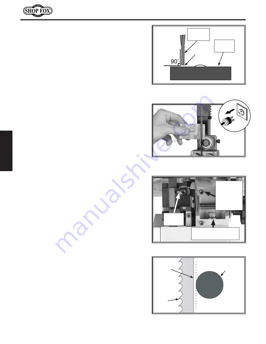
3. Loosen the guide block assembly cap screws and
rotate the blade guide assembly side-to-side, until
the blade is perpendicular with the face of the
support bearing, as illustrated in
Figure
36
.
4. Tighten the guide block assembly cap screws.
5. Loosen the bolt on the support bearing adjustment
shaft—if it is not already loose.
6. Using a feeler gauge between the support bearing
and the blade, position the bearing 0.016" away from
the back of the blade, as illustrated in
Figure
36
.
.
Note:.
For a quick gauge, fold a crisp dollar bill
in half twice (four thicknesses of a dollar bill is
approximately 0.016") and place it between the
support bearing and the blade, as illustrated in
Figure 37
.
7.
Tighten the cap screw to keep the support bearing
locked in place.
Figure
36
. Blade set perpendicular (90˚)
to the support bearing face.
Support
Bearing
Bandsaw
Blade
0.016"
Gap
Figure
37
. Example of using a dollar bill as
a 0.016" gauge.
To.adjust.the.lower.support.bearing,.do.these.steps
:
1.
DISCONNECT BANDSAW FROM POWER!
2.
Familiarize yourself with the lower support bearing
controls shown in
Figure.38
.
3.
Open the upper and lower wheel covers.
4. Loosen the cap screw on the support bearing
adjustment shaft.
5.
Using a feeler gauge, position the support bearing
0.016" away from the back of the blade, as
illustrated in
Figure
39
, or use a dollar bill (see
Figure.37
).
6. Tighten the cap screw to keep the support bearing
locked in place.
Figure
38
. Lower support bearing controls.
Support
Bearing
Adjustment
Shaft Cap
Screw
Support
Bearing
Guide Block
Assembly Cap Screw
Figure
39
. Blade aligned 0.016" away from
the support bearing edge.
0.016"
Gap
Support
Bearing
Blade
Содержание W1825
Страница 73: ...Model W1825 For Machines Mfd Since 07 15...
Страница 76: ......


