YQE8-J0093E
5
Maintenance Parts Replacement Procedures
1
/
1
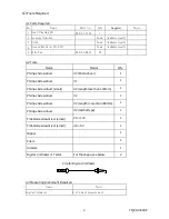
Parts
Name
PCB HSSV7-CONT-F ASSY
Part No.
164-11-09756
Tools
Phillips Screwdriver (#2)
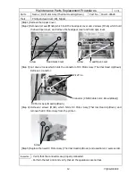
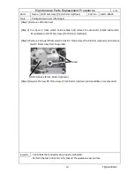
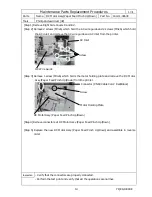
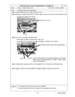
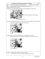
[Step 1] Remove Side Covers L and R and Front Cover.
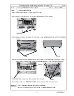
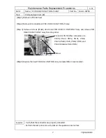
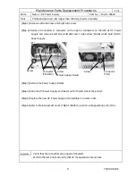
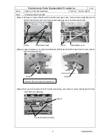
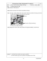
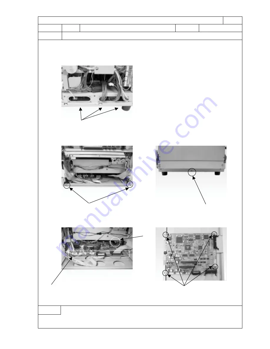
[Step 2] Remove 3 connectors at the left side of PCB HSSV7-CONT-F Assy.
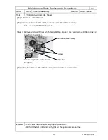
[Step 3] Remove 2 screws (M3x6) at the front and 1 screw on the back (M3x6), which hold the PCB
Holder.
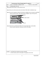
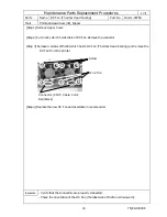
[Step 4] Pull the PCB Holder slightly to the front, remove 8 connectors at PCB HSSV7-CONT-F
Assy, remove 4 screws, then remove PCB HSSV7-CONT-F Assy from the PCB Holder.
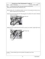
[Step 5] Replace the new PCB HSSV7-CONT-F Assy and assemble in reverse order.
Inspection
- Verify that the connectors are properly connected.
- Perform the test print and verify that all the operations are normal.
Connector
Screw
Screw
Screw
CN18
CN8 CN12
CN7, CN6, CN10, CN9, CN14, CN4, and CN13 from the left
CN3


