YQE8-J0093E
30
Maintenance Parts Replacement Procedures
2
/
2
Part
Name
Feed Roller Guide Assy
Part No.
164-11-09761
Tools
Phillips Screwdriver (#2), Phillips Screwdriver (#2, shorter than 100mm), Flat-blade
Screwdriver (2.5x100), Pliers
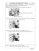
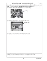
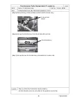
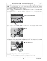
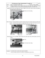
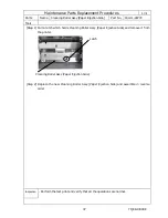
[Step 6] Remove 2 screws which hold PCB HSSV7-JUNCTION-F Assy and 2 screws which hold the
gear line cover. Removing connectors and cables is not required. (Refer to the
explanation of [Step 3] on Page 21 of this document)
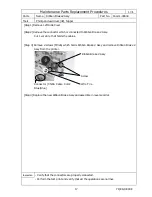
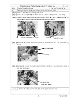
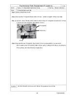
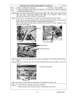
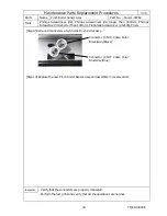
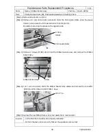
[Step 7] Remove the E ring and sleeve on the right side which hold the Feed Pinch Roller.
Remove the E ring which holds Gear 55 on the left side of the printer and remove Gear 55.
Remove the E ring on the left side which holds the Feed Pinch Roller.
Take out the hook of screw spring, slide the entire Feed Pinch Roller rightward, and
remove it from the printer.
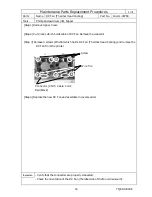
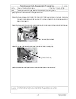
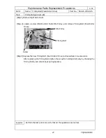
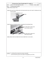
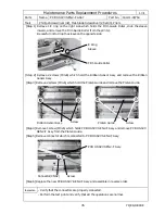
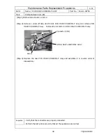
[Step 8] Remove the connector (CN46) of Feed Roller Guide Assy from PB HSSV7-JUNCTION-F
Assy.
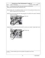
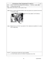
[Step 9] Remove 2 screws (M3x6) which hold Feed Roller Guide Assy and remove it from the
printer.
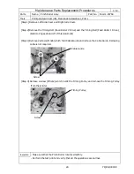
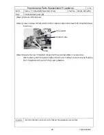
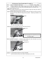
[Step 10] Remove the new Feed Roller Guide Assy and assemble in reverse order.
Inspection
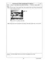
- Verify that the connectors are properly connected.
- Perform the test print and verify that all the operations are normal.
Screw
Feed Roller Guide Assy
E Ring and Sleave
Gear 55
E Ring
E Ring
Feed Pinch Roller
Screw Spring

