YQE8-J0093E
32
Maintenance Parts Replacement Procedures
1
/
3
Parts
Name
Pinch Roller Sensor Assy
Part No.
164-11-09762
Tools
Phillips Screwdriver (#2), Phillips Screwdriver (#2, longer than 300mm), Phillips
Screwdriver (#2, shorter than 100mm), Flat-blade Screwdriver (2.5x100), Pliers
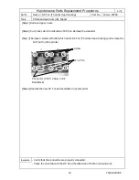
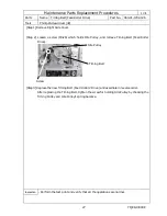
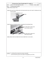
[Step 1] Remove Right Side Cover.
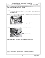
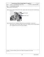
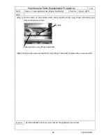
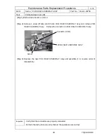
[Step 2] Pull a latch at the center which holds Cleaning Roller (Paper Feed Side) and remove the
Cleaning Roller from the printer to the front.
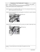
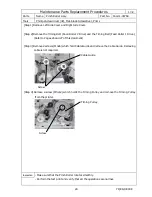
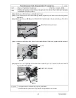
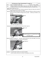
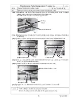
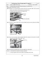
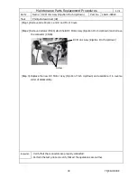
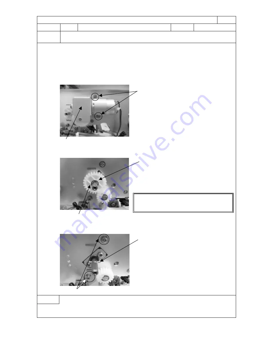
[Step 3] Remove 2 screws (M3x6) which holds the DC Motor Assy (Ribbon Winding) and remove
the DC Motor Assy (Ribbon Winding) from the printer. (Removing connectors is not
required.)
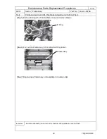
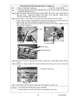
[Step 4] Remove 1 E ring which holds Gear 26 and remove Gear 26.
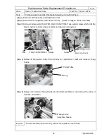
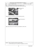
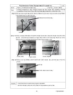
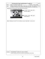
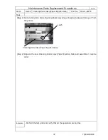
[Step 5] Remove the Parallel Pin. Remove 2 screws (M3x6) which hold the Ribbon Core Holder
and remove the Ribbon Core Holder from the printer.
Inspection
- Verify that the connectors are properly connected.
- Perform the test print and verify that all the operations are normal.
E Ring
Caution: Be careful not to drop the pin when
removing the gear.
Screw
DC Motor Assy (Ribbon Winding)
Gear 26
Screw
Parallel Pin

