46(178)
3.4.5 Emergency Stop
Hand Controller has emergency stop button to stop the robot. Once the button pressed, the
robot will stop but the gripper and vacuum valve will still function to prevent dropping parts
from the gripper. Moreover, the hand controller will remain power and indicate an error
message. When the robot malfunction or need to under maintenance, press the emergency
stop button to ensure operation safety.
3.5 Default Settings
1) The traverse speed is at 85% of the full speed.
2) The pressure sensor switch is at 4bar, when air pressure is less than 4bar, the machine
will stop working and alarm.
3) The filter valve is at 6bar.
4) The vacuum pressure sensor is at -60.
3.6 ST3(5) Robot Reversing
The following paragraph is the instruction for reversing ST3(5) robot dropping side (Operation
side to non-operation side). For safety, please turn off the electrical power and pneumatic
supply before operating.
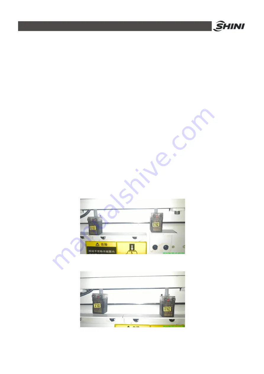
1) Unscrew the proximity sensor X103 and move it up to the same level as X102, then screw
X103. Unscrew the proximity sensor X102 and move it down to the same level as where
X103 was, and then screw X102. See
错误!未找到引用源。
and
错误!未找到引用源。
.
Fig.3-3: Sensor position before modifying
Fig.3-4: Sensor position after modifying
Содержание ST3 Series
Страница 1: ...ST3 5 Fully Servo Driven Robot User Manual Date Jun 2016 Version V1 5 English ...
Страница 2: ...2 178 ...
Страница 12: ...12 178 ...
Страница 105: ...105 178 7 Assembly Diagram 7 1 ST3 ST3 T traverse Unit Fig 7 1 ST3 ST3 T traverse unit small model exploded view ...
Страница 109: ...109 178 7 3 ST3 ST5 D Main arm Unit single stage arm Fig 7 4 ST3 Main arm unit single stage arm exploded view ...
Страница 111: ...111 178 7 4 ST3 T ST5 DT Main arm unit Telescopic arm Fig 7 5 ST3 T Main arm unit telescopic arm exploded view ...
Страница 117: ...117 178 7 7 ST5 D Sub Arm unit Single stage arm Fig 7 9 ST5 Sub arm unit single stage arm exploded view ...
Страница 121: ...121 178 7 9 ST3 MT Traverse unit Fig 7 11 ST3 MT traverse unit exploded view ...
Страница 123: ...123 178 7 10 ST3 MT Crosswise Unit Fig 7 12 ST3 MT crosswise Unit exploded view ...
Страница 125: ...125 178 7 11ST3 MT Main arm unit Fig 7 13 ST3 MT Main arm unit telescopic arm exploded view ...
Страница 130: ...130 178 7 13 ST3 LT Crosswise Unit Fig 7 15 ST3 LT crosswise unit exploded view ...
Страница 132: ...132 178 7 14 ST3 LT Main arm unit Fig 7 16 ST3 LT main arm unit exploded view ...
Страница 137: ...137 178 9 2 ST3 Each I O module electrical wiring diagram Fig 9 2 ST3 Each I O module wiring diagram ...
Страница 144: ...144 178 9 9 ST3 Intermediate relay wiring diagram Fig 9 9 ST3 Intermediate relay wiring diagram ...
Страница 148: ...148 178 9 13 ST3 EM67 input signal wiring diagram Fig 9 13 ST3 EM67 input signal wiring diagram ...
Страница 149: ...149 178 9 14 ST3 EM67 output signal wiring diagram Fig 9 14 ST3 EM67 output signal wiring diagram ...
Страница 150: ...150 178 9 15 ST3 SIGMATEK module board Fig 9 15 ST3 SIGMATEK Module board 1 ...
Страница 151: ...151 178 Fig 9 16 ST3 SIGMATEK Module board 2 ...
Страница 155: ...155 178 10 2 ST5 Each I O module electrical wiring diagram Fig 10 2 ST5 Each I O module electrical wiring diagram ...
Страница 160: ...160 178 吸盘3电磁阀 吸盘4电磁阀 夹具3电磁阀 夹具4电磁阀 垂直电磁阀 水平电磁阀 备用3 Fig 10 7 ST5 Sub arm unit output signal wiring diagram ...
Страница 161: ...161 178 黄棕 红蓝 粉 粉灰 黑 绿 黄白 白 红 灰白 黄 棕 棕绿 灰 Fig 10 8 ST5 Axis Z servo driver I O signal wiring diagram ...
Страница 166: ...166 178 10 11ST5 Intermediate relay wiring diagram Fig 10 13 ST5 Intermediate relay wiring diagram ...
Страница 167: ...167 178 10 12ST5 EM67 input signal wiring diagram Fig 10 14 ST5 EM67 input signal wiring diagram ...
Страница 168: ...168 178 10 13ST5 EM67 output signal wiring diagram Fig 10 15 ST5 EM67 output signal wiring diagram ...
Страница 174: ...174 178 10 19 ST5 SIGMATEK module board Fig 10 21 ST5 SIGMATEK module board 1 ...
Страница 175: ...175 178 Fig 10 22 ST5 SIGMATEK module board 2 ...


