36(178)
vi.
Press
“
Mode
”
once back to measurement mode.
2) Pressure value range settings
i.
The lower limit: for example
“
-50
”
, press
“
Mode
”
screen display
“
L0-1
”
, press
up/down set the valve to
“
-50
”
.
ii.
The upper limit: for example
“
-20
”
, press
“
Mode
”
screen display
“
H1-1
”
, press
up/down set the valve to
“
-50
”
.
Note: if the lower limit absolute value smaller than the upper limit absolute value,
pressure switch will display pressure
“
DOWN
”
error message.
3) Lock button
After setting value, press
“
Mode
”
and
“
down
”
keys together till screen displays LOCK,
ON
”
. This operation is preventing error change pressure value.
4) Remove lock button
Press
“
Mode
”
and
“
down
”
keys together till screen display
“
LOCK, OFF
”
.
2.5
Robot and IMM Interface
ST3(5) series robots are available with 2 different interface versions to communicate with the
injection moulding machine:
o
Euromap67
o
Euromap12
Both versions are described in the following chapters.
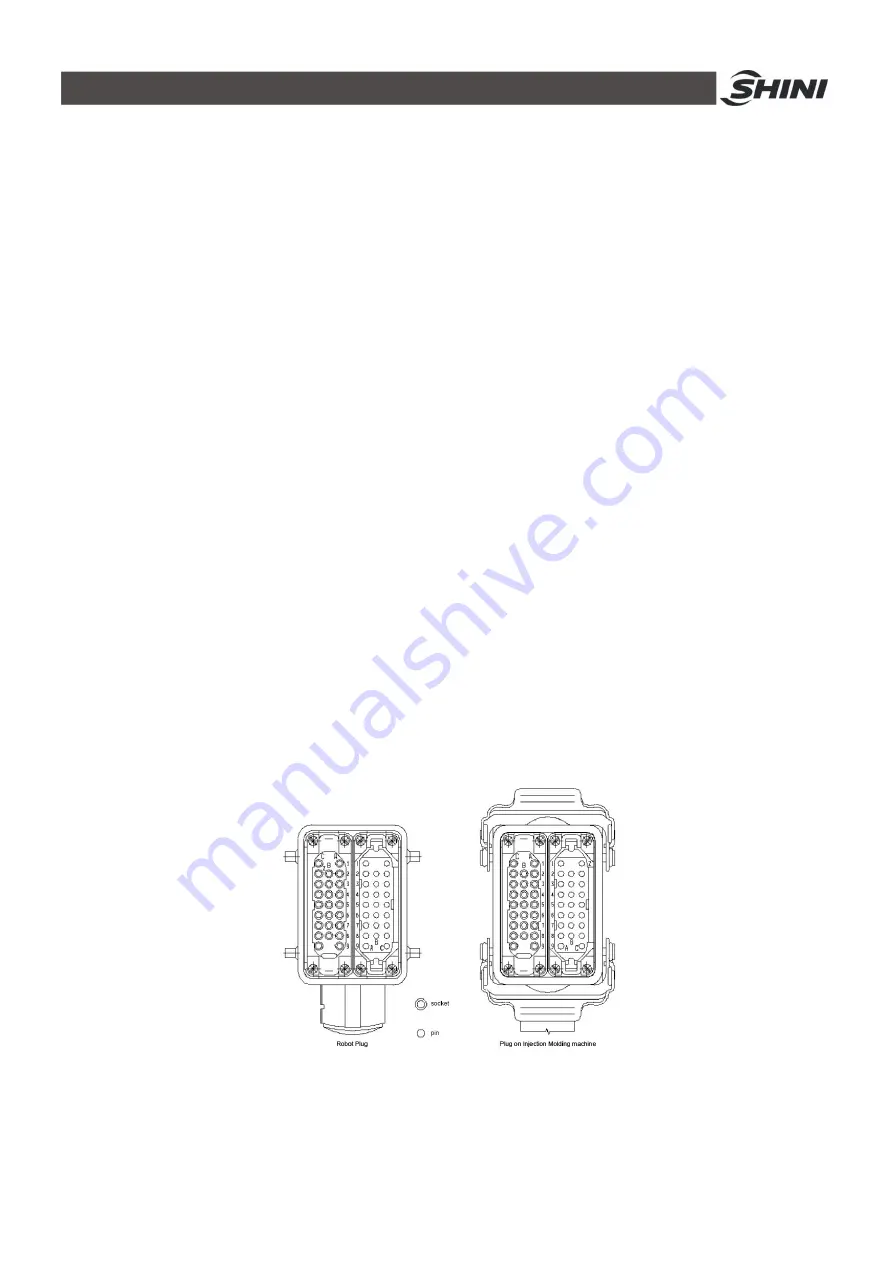
2.5.1 Euromap67 Interface
Euromap67 interface defines the connection plug between the injection moulding machine
and the robot:
Fig.2-14: Euromap 67 interface plug
The robot-injection moulding machine interface is designed according to the directives of
Euromap67, which states:
All signals are continuous signals unless otherwise noted.
Содержание ST3 Series
Страница 1: ...ST3 5 Fully Servo Driven Robot User Manual Date Jun 2016 Version V1 5 English ...
Страница 2: ...2 178 ...
Страница 12: ...12 178 ...
Страница 105: ...105 178 7 Assembly Diagram 7 1 ST3 ST3 T traverse Unit Fig 7 1 ST3 ST3 T traverse unit small model exploded view ...
Страница 109: ...109 178 7 3 ST3 ST5 D Main arm Unit single stage arm Fig 7 4 ST3 Main arm unit single stage arm exploded view ...
Страница 111: ...111 178 7 4 ST3 T ST5 DT Main arm unit Telescopic arm Fig 7 5 ST3 T Main arm unit telescopic arm exploded view ...
Страница 117: ...117 178 7 7 ST5 D Sub Arm unit Single stage arm Fig 7 9 ST5 Sub arm unit single stage arm exploded view ...
Страница 121: ...121 178 7 9 ST3 MT Traverse unit Fig 7 11 ST3 MT traverse unit exploded view ...
Страница 123: ...123 178 7 10 ST3 MT Crosswise Unit Fig 7 12 ST3 MT crosswise Unit exploded view ...
Страница 125: ...125 178 7 11ST3 MT Main arm unit Fig 7 13 ST3 MT Main arm unit telescopic arm exploded view ...
Страница 130: ...130 178 7 13 ST3 LT Crosswise Unit Fig 7 15 ST3 LT crosswise unit exploded view ...
Страница 132: ...132 178 7 14 ST3 LT Main arm unit Fig 7 16 ST3 LT main arm unit exploded view ...
Страница 137: ...137 178 9 2 ST3 Each I O module electrical wiring diagram Fig 9 2 ST3 Each I O module wiring diagram ...
Страница 144: ...144 178 9 9 ST3 Intermediate relay wiring diagram Fig 9 9 ST3 Intermediate relay wiring diagram ...
Страница 148: ...148 178 9 13 ST3 EM67 input signal wiring diagram Fig 9 13 ST3 EM67 input signal wiring diagram ...
Страница 149: ...149 178 9 14 ST3 EM67 output signal wiring diagram Fig 9 14 ST3 EM67 output signal wiring diagram ...
Страница 150: ...150 178 9 15 ST3 SIGMATEK module board Fig 9 15 ST3 SIGMATEK Module board 1 ...
Страница 151: ...151 178 Fig 9 16 ST3 SIGMATEK Module board 2 ...
Страница 155: ...155 178 10 2 ST5 Each I O module electrical wiring diagram Fig 10 2 ST5 Each I O module electrical wiring diagram ...
Страница 160: ...160 178 吸盘3电磁阀 吸盘4电磁阀 夹具3电磁阀 夹具4电磁阀 垂直电磁阀 水平电磁阀 备用3 Fig 10 7 ST5 Sub arm unit output signal wiring diagram ...
Страница 161: ...161 178 黄棕 红蓝 粉 粉灰 黑 绿 黄白 白 红 灰白 黄 棕 棕绿 灰 Fig 10 8 ST5 Axis Z servo driver I O signal wiring diagram ...
Страница 166: ...166 178 10 11ST5 Intermediate relay wiring diagram Fig 10 13 ST5 Intermediate relay wiring diagram ...
Страница 167: ...167 178 10 12ST5 EM67 input signal wiring diagram Fig 10 14 ST5 EM67 input signal wiring diagram ...
Страница 168: ...168 178 10 13ST5 EM67 output signal wiring diagram Fig 10 15 ST5 EM67 output signal wiring diagram ...
Страница 174: ...174 178 10 19 ST5 SIGMATEK module board Fig 10 21 ST5 SIGMATEK module board 1 ...
Страница 175: ...175 178 Fig 10 22 ST5 SIGMATEK module board 2 ...


