77(178)
4.3.7 System Setup
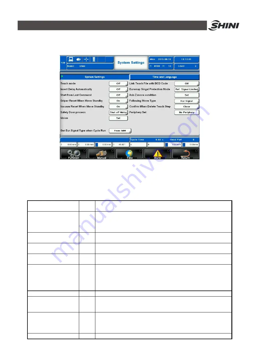
Click
Function--System Setup
to enter the page as shown in Fig.4-43.
Fig.4-43: System Setup page
4.3.7.1 System Settings
The details of system settings bar as shown in Table 4-3.
Table 4-3: System settings details
Teach mode
On
Off
On
à
All position can only be inserted by manual teach mode
Off
à
All position can be inserted by manual input
Insert Delay Automatically
On
Off
On
à
During teach motion, system will insert a delay automatically for every
new inserted motion
Off
à
No delay command will be inserted, if user need a delay, need to insert
manually
Start from last Command
On
Off
On
à
Able to continue operation after alarm
Off
à
No further operation after alarm
Gripper reset when move
standby
On
Off
On
à
After troubleshooting, gripper restore to position automatically
Off
à
After troubleshooting, gripper need to restore to position manually
Vacuum reset when move
standby
On
Off
On
à
After troubleshooting, vacuum restore to the position automatically
Off
à
After troubleshooting, vacuum need to restore to the position manually
Safety door process
Set safety door alarm way during automatic operation
-- Switch to manual
-- Switch to semi-automation
-- Decrease turn to semi-automation
-- Shut off motor
Vision
Set whether to enable outside vision
Get Eur.Signal type when
cycle run
Choose machine input EUROMAP signal source
-- From IMM
-- From simulator
Euromap signal protection
mode
Set Euromap output signal limit tuning
-- Arm origin
-- Standby point
-- Safe point
Axis Z move condition
Set condition for axis Z movement
Содержание ST3 Series
Страница 1: ...ST3 5 Fully Servo Driven Robot User Manual Date Jun 2016 Version V1 5 English ...
Страница 2: ...2 178 ...
Страница 12: ...12 178 ...
Страница 105: ...105 178 7 Assembly Diagram 7 1 ST3 ST3 T traverse Unit Fig 7 1 ST3 ST3 T traverse unit small model exploded view ...
Страница 109: ...109 178 7 3 ST3 ST5 D Main arm Unit single stage arm Fig 7 4 ST3 Main arm unit single stage arm exploded view ...
Страница 111: ...111 178 7 4 ST3 T ST5 DT Main arm unit Telescopic arm Fig 7 5 ST3 T Main arm unit telescopic arm exploded view ...
Страница 117: ...117 178 7 7 ST5 D Sub Arm unit Single stage arm Fig 7 9 ST5 Sub arm unit single stage arm exploded view ...
Страница 121: ...121 178 7 9 ST3 MT Traverse unit Fig 7 11 ST3 MT traverse unit exploded view ...
Страница 123: ...123 178 7 10 ST3 MT Crosswise Unit Fig 7 12 ST3 MT crosswise Unit exploded view ...
Страница 125: ...125 178 7 11ST3 MT Main arm unit Fig 7 13 ST3 MT Main arm unit telescopic arm exploded view ...
Страница 130: ...130 178 7 13 ST3 LT Crosswise Unit Fig 7 15 ST3 LT crosswise unit exploded view ...
Страница 132: ...132 178 7 14 ST3 LT Main arm unit Fig 7 16 ST3 LT main arm unit exploded view ...
Страница 137: ...137 178 9 2 ST3 Each I O module electrical wiring diagram Fig 9 2 ST3 Each I O module wiring diagram ...
Страница 144: ...144 178 9 9 ST3 Intermediate relay wiring diagram Fig 9 9 ST3 Intermediate relay wiring diagram ...
Страница 148: ...148 178 9 13 ST3 EM67 input signal wiring diagram Fig 9 13 ST3 EM67 input signal wiring diagram ...
Страница 149: ...149 178 9 14 ST3 EM67 output signal wiring diagram Fig 9 14 ST3 EM67 output signal wiring diagram ...
Страница 150: ...150 178 9 15 ST3 SIGMATEK module board Fig 9 15 ST3 SIGMATEK Module board 1 ...
Страница 151: ...151 178 Fig 9 16 ST3 SIGMATEK Module board 2 ...
Страница 155: ...155 178 10 2 ST5 Each I O module electrical wiring diagram Fig 10 2 ST5 Each I O module electrical wiring diagram ...
Страница 160: ...160 178 吸盘3电磁阀 吸盘4电磁阀 夹具3电磁阀 夹具4电磁阀 垂直电磁阀 水平电磁阀 备用3 Fig 10 7 ST5 Sub arm unit output signal wiring diagram ...
Страница 161: ...161 178 黄棕 红蓝 粉 粉灰 黑 绿 黄白 白 红 灰白 黄 棕 棕绿 灰 Fig 10 8 ST5 Axis Z servo driver I O signal wiring diagram ...
Страница 166: ...166 178 10 11ST5 Intermediate relay wiring diagram Fig 10 13 ST5 Intermediate relay wiring diagram ...
Страница 167: ...167 178 10 12ST5 EM67 input signal wiring diagram Fig 10 14 ST5 EM67 input signal wiring diagram ...
Страница 168: ...168 178 10 13ST5 EM67 output signal wiring diagram Fig 10 15 ST5 EM67 output signal wiring diagram ...
Страница 174: ...174 178 10 19 ST5 SIGMATEK module board Fig 10 21 ST5 SIGMATEK module board 1 ...
Страница 175: ...175 178 Fig 10 22 ST5 SIGMATEK module board 2 ...


