6
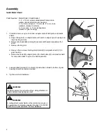
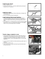
Install Handlebar Bracket and Handlebar
1. Install lower handlebar cap (S) and handle bar mounting bracket (T)
on outer drive shaft tube (U) using (2) 5 mm x 25 mm socket head cap
screws. Do not tighten screws securely until final adjustments are com
-
pleted.
2. Place handle bar (V) in mounting bracket, and secure with upper handlebar
cap (W) and (4) 5 mm x 25 mm socket head cap screws. Do not tighten
screws securely until final adjustments are completed.
T
J
S
W
V
Install Harness Hanger
1. Remove handle shim (P).
2. Slide harness hanger (Q) on to outer drive shaft tube (R) and loosely at-
tach with 5 mm x 12 mm screw.
Install Power Head
1. Slide outer drive shaft assembly into power head clamp, and align power
head with gear case.
2. Secure drive shaft assembly with clamping bolt.
1. Thread throttle cable adjusment fixture (K) into throttle cable bracket (L),
and install wire end (I) into large carburetor swivel hole. Check throttle
for freedom of movement and that wide open throttle/low idle extremes
are adjusted properly. Turn the cable adjusment fixture in or out to make
adjustments.
2. Connect 2 ignition stop leads from throttle cable tubing to ignition leads on
engine (J).
3. Reinstall the air cleaner cover.
4. Route throttle linkage and ignition lead assembly behind handle bracket
and clip to drive shaft.
Throttle Linkage and Ignition Leads
Q
R
P
I
K
L
K
J
Содержание BCK-11
Страница 10: ...10 NOTES...
Страница 11: ...11 NOTES...


