Shimadzu OMRON CJ Series Скачать руководство пользователя страница 55

9

Program 

  52 

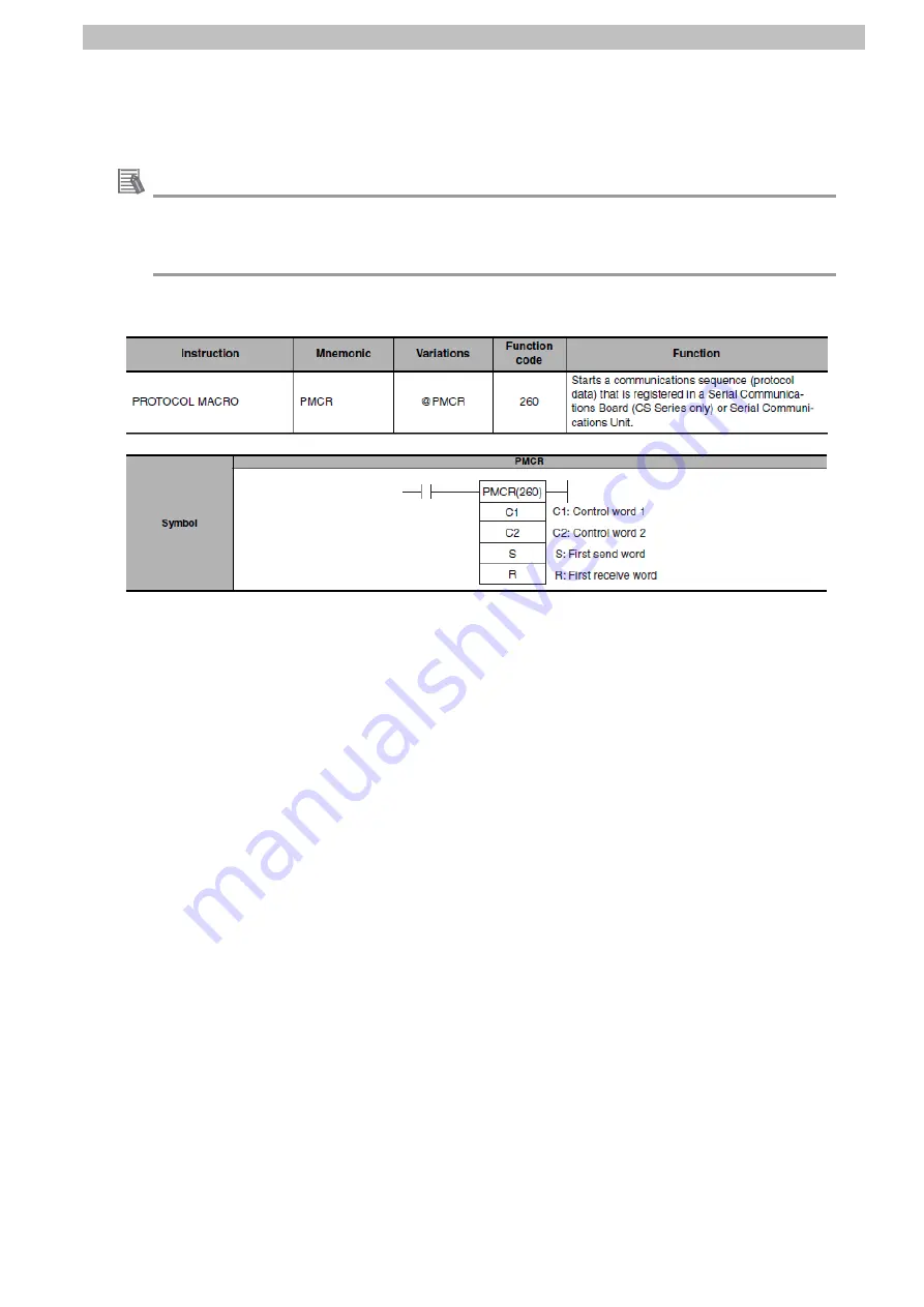
9.1.2. PMCR Instruction and Send/Receive Messages 

The basic operations of the PMCR instruction and send/receive messages are given below.   


Additional Information 

For details, refer to 

Serial Communications Instructions (PMCR)

 in 

SECTION 3 Instructions 

of the 

CJ Series Programmable Controllers INSTRUCTIONS REFERENCE MANUAL

 (Cat. 

No. W474). 


PMCR instruction operand data 


Содержание OMRON CJ Series

Страница 1: ...Programmable Controller CJ series General purpose Serial Connection Guide RS 232C SHIMADZU CORPORATION Shimadzu Analytical Balance Electronic Balance ATX R ATY R UPX UPY UW UX Series P732 E1 01...

Страница 2: ...en shots reprinted with permission from Microsoft Corporation Windows is a registered trademark of Microsoft Corporation in the USA and other countries Company names and product names in this guide ar...

Страница 3: ...al Communications Connection Procedure 11 7 1 Work Flow 11 7 2 SHIMADZU Balance Setup 13 7 3 PLC Setup 21 7 4 Serial Communication Status Check 40 8 Initialization Method 48 8 1 Initializing a PLC 48...

Страница 4: ...CJ2H CPU6 EIP CJ Series CJ2 CPU Unit Hardware USER S MANUAL OMRON W473 CJ2M CPU CJ2H CPU6 CJ2H CPU6 EIP CJ Series CJ2 CPU Unit Software USER S MANUAL OMRON W336 CJ1W SCU 1 V1 CJ1W SCU 2 CJ Series Seri...

Страница 5: ...a program The sequence started by the instruction executes its steps in a given order step A unit to execute any one of the followings message send processing message receive processing message send r...

Страница 6: ...It is subject to change for improvement without notice The following notations are used in this guide Indicates a potentially hazardous situation which if not avoided may result in minor or moderate...

Страница 7: ...single output with stability information and receiving a response PLC Serial communications RS 232C Balance Sends command data Executes the command Receives response data and stores in memory Returns...

Страница 8: ...e used as examples of applicable devices to describe the procedures for connecting the devices and checking their connection You cannot use devices with versions lower than those listed in 5 2 To use...

Страница 9: ...Windows 10 USB cable USB 2 0 compliant USB B connector Serial cable RS 232C SHIMADZU Balance ATX324R SHIMADZU AC Adapter supplied with the Balance Precautions for Correct Use Contact OMRON to obtain l...

Страница 10: ...85 Wiring of the CJ Series Serial Communications Units OPERATION MANUAL Cat No W336 Additional Information The system configuration in this guide uses USB for the connection between the personal compu...

Страница 11: ...are all set at once data bit length stop bit length parity baud rate communication speed handshake and data format For details on the communication settings refer to 10 CONNECTION AND COMMUNICATION o...

Страница 12: ...to send Input 6 5V Power supply 7 DR Data set ready Input 8 ER Data terminal ready Output 9 SG Signal ground Shell FG Shield ATX R ATY R series applicable connector D SUB 9 pin male Use Pin No Abbrevi...

Страница 13: ...o RTS 6 DSR Handshake receive 7 SG Signal ground 8 to 19 Undefined 20 DTR Handshake send 21 to 25 Undefined Cable and pin layout Serial Communications Unit CJ1W SCU42 UPX UPY UW UX series RS 232C Inte...

Страница 14: ...1 Parameter Settings Set parameters for the Balance 7 3 PLC Setup Set up the PLC 7 3 1 Hardware Settings Set the hardware switches on the Serial Communications Unit and connect the cables 7 3 2 Openi...

Страница 15: ...y 7 4 1 Starting the Trace Start tracing with CX Protocol 7 4 2 Executing the Communications Sequence Execute the communications sequence with CX Programmer 7 4 3 Checking the Trace Data Check with th...

Страница 16: ...series Set parameters for ATX R ATY R series Precautions for Correct Use Make sure the power supply is OFF before setting up If it is ON the settings described in the following steps and subsequent pr...

Страница 17: ...l shows MODE 2 Press O T key once In this guide the communication specifications of Balance are set to MODE 2 standard settings 2 in order to send command data from PLC to Balance and check response d...

Страница 18: ...7 Serial Communications Connection Procedure 15 8 Display panel shows gram units Press BREAK key 9 Display panel shows READY Balance is in the standby mode 10 Turn OFF AC Adapter...

Страница 19: ...FF 2 Check the position of the connectors on Balance Connect a Serial cable RS 232C to RS 232C connector Connect AC Adapter to DC IN connector Back view of Balance 3 Check the position of the operatio...

Страница 20: ...linking of indicates the menu group 1 Press CAL key to move to the next menu group The analog display blinks Check that is blinking Press O T key Set the communication specifications by following the...

Страница 21: ...dshake to OFF 10 Check that the stability mark is displayed to the left of H oFF Press POWER key The handshake is set to OFF 11 Display panel shows HFbPSd Press CAL key Check that F is blinking Press...

Страница 22: ...Sd Press CAL key Check that P is blinking Press O T key 16 Check that the stability mark is displayed to the left of P no Press POWER key The parity bit length is set to none 8 bits 17 Display panel s...

Страница 23: ...20 20 Check that the stability mark is displayed to the left of d Cr Press and hold POWER key for about 3 seconds The delimiter is set to CR 21 Display panel shows gram units Press POWER key 22 Displa...

Страница 24: ...ure PLC is powered OFF 2 Check the positions of the hardware switches and Port 2 on the front panel of Serial Communications Unit by referring to the figure on the right 3 Set Unit number switch to 0...

Страница 25: ...ng 1 Turn ON PLC and AC Adapter on Balance 2 Start CX Programmer If the User Account Control Dialog Box is displayed at start make a selection to start CX Programmer 3 CX Programmer starts up 4 Select...

Страница 26: ...ialog Box is displayed Select the device type of PLC from the pull down list in the Device Type Field Click Settings CJ2M is selected in this guide 9 The Device Type Settings Dialog Box is displayed S...

Страница 27: ...d the device type in step 8 or the CPU type in step 9 the dialog box on the right will be displayed Confirm that there is no problem and click Yes Make sure the program is converted normally 0 errors...

Страница 28: ...ch as the connection type described in steps 7 through to 9 and then try online again For more information refer to Connecting Directly to a CJ2 CPU Unit Using a USB Cable of the CX Programmer OPERATI...

Страница 29: ...ogram from the PLC Menu in CX Programmer 2 The dialog box on the right is displayed Confirm that there is no problem and click Yes Refer to Additional Information on the previous page for the settings...

Страница 30: ...Confirm that there is no problem and click Yes The dialog box on the right is displayed Confirm that there is no problem and click Yes 4 The Transfer from PLC Dialog Box is displayed Select IO Table a...

Страница 31: ...in Rack in the PLC IO Table Window to expand the tree 2 Right click 00 1500 CJ1W SCU42 and select Unit Setup from the menu 3 The View Parameters Dialog Box is displayed Select Port2 Protocol macro Set...

Страница 32: ...ault values 5 Select User settings from the pull down list in the Port2 Port settings Field 6 Set the following parameters in the same way as step 5 Serial communications mode Protocol macro Data leng...

Страница 33: ...o problem and click Yes Check that the transfer is complete as shown on the right Click Close 8 The dialog box on the right is displayed Check the contents and click Yes The Select Port Dialog Box is...

Страница 34: ...are in the View Parameters Dialog Box 11 Check that a message is displayed stating Compare successful as shown in the figure on the right Click Close 12 Click OK in the View Parameters Dialog Box 13 S...

Страница 35: ...am s Comments and Program index Click OK You do not need to transfer I O table and Special Unit Setup because they are already set in 7 3 3 Creating an I O Table and 7 3 4 Parameter Settings The Comme...

Страница 36: ...wnload successful is displayed after the transfer is complete Click OK 5 Select Programs in the project workspace Select Transfer Compare with PLC from the PLC Menu 6 Select Program s and click OK 7 C...

Страница 37: ...CX Protocol 2 Start CX Protocol The following panes are displayed in the window Upper left Project Workspace Lower left Output Window Right Project Window 3 Select Open from the File Menu 4 The Open D...

Страница 38: ..._ E Balance_V100 in the Project Workspace to expand the tree 2 Select Edit PC PLC Comms Settings from the PLC Menu 3 The Change PLC Dialog Box is displayed Select the PLC type from the pull down list...

Страница 39: ...Program in the Project Workspace It means that PLC is online If the other operating mode such as Monitor or Run is displayed change it to Program by following step 8 8 If the operating mode is Monito...

Страница 40: ...down list as shown in the figure on the right 11 Click New Protocol List in the Project Workspace and select Download Protocols from the Protocol Menu 12 The dialog box on the right is displayed Sele...

Страница 41: ...nfirm that there is no problem and click OK 15 Check that 100 is displayed in the Downloaded Column as shown in the figure on the right Click Close 16 Select Compare Protocols from the Protocol Menu 1...

Страница 42: ...ed in the Complied Column Click Compare after checking that the compile is complete 19 The dialog box on the right is displayed Check that Successful is displayed in the Result Column Click OK 20 Chec...

Страница 43: ...ng power flow and present values in the Ladder Section Window or in the Watch Window Precautions for Correct Use Make sure the serial cable is connected before following the procedures described herea...

Страница 44: ...ect Window Check that Trace 2 is highlighted as shown in the figure on the right Trace 2 corresponds to Port 2 of Serial Communications Unit 6 Select Start Trace One Shot Trace from the PLC Menu 7 Che...

Страница 45: ...adder Section Window shows the Section1 ladder program 2 Press POWER key to show gram units on Display panel on Balance Check that 0 0000 g is displayed 3 Place a sample substance to be measured on th...

Страница 46: ...ommunications Connection Procedure 43 5 In the Ladder Section Window right click Input_Start and select Set On from the menu 6 Check that the Input_Start contact is turned ON as shown in the figure on...

Страница 47: ...k with the trace data in CX Protocol that correct data is sent and received 1 Select Upload Trace from the PLC Menu in CX Protocol Once the trace data is stored the menu item Upload Trace becomes sele...

Страница 48: ...f 7 4 2 Executing the Communications Sequence The above mentioned indicates a space The contents of the response data and parameters are shown on the right For more information refer to 10 CONNECTION...

Страница 49: ...f the PLC 1 Select Edit Memory from the PLC Menu in CX Programmer 2 Double click CIO in the Memory Tab of the PLC Memory Window 3 Enter 5500 in the Start Address Field of the CIO Area Check that the s...

Страница 50: ...the trace data displayed in step 3 of 7 4 3 Checking the Trace Data The above mentioned indicates a space 20 in hexadecimal The number of words being used 0008 in hexadecimal is stored in word CIO5500...

Страница 51: ...ial Communications Unit and a CPU Unit Change the operating mode of the PLC to PROGRAM mode before the initialization 8 1 1 Serial Communications Unit To initialize a Serial Communications Unit select...

Страница 52: ...IMADZU Balance For information on how to initialize a SHIMADZU Balance refer to the following manuals UW UX series 7 5 2 Returning to the Default Settings menu reset of the Electronic Balance Instruct...

Страница 53: ...al or error end of the send receive processing The normal end of the send receive processing means a normal end of the communications sequence The error end means an error end of the communications se...

Страница 54: ...ommand by receiving the command data from the PLC and returns response data to the PLC 4 The PLC receives the response data from the Balance according to the receive message defined by the communicati...

Страница 55: ...the PMCR instruction and send receive messages are given below Additional Information For details refer to Serial Communications Instructions PMCR in SECTION 3 Instructions of the CJ Series Programmab...

Страница 56: ...03E7 0 15 Bit Wd Word S First send word send area specification The first word of the words required to send data is specified S contains the number of words n to be sent 1 i e including the S word Fr...

Страница 57: ...d and send message SCU to Destination Device Send message CPU to SCU Send area S Wd 0 Wd 1 Wd 2 Wd n 1 0 15 0 15 0 15 0 15 Bit The number of words CR LF Terminator Data Wd Word Relationship between re...

Страница 58: ...84 single output with stability information are shown below Control word C1 setting C1 CIO 5010 Word Contents data type Data description C1 Communications port No 1 digit hex 7210 Communications port...

Страница 59: ...ch is used for receiving the value acquired from the Destination Device by using the command single output with stability information The following items are stored in order from R 1 R CIO 5500 Item S...

Страница 60: ...unmatched baud rate setting are detected as communications errors If an error occurs the Sequence Abort End Completion flag 1519 10 in the CIO area allocated to the SCU will be turned ON to identify...

Страница 61: ...cription 5000 02 BOOL Output_NormalEnd Turns ON when the send receive processing ends normally 5000 03 BOOL Output_ErrorEnd Turns ON when one or more of the following errors occurs 1 PMCR instruction...

Страница 62: ...5000 06 BOOL Local_DestinationDevice Error Turns ON when a Destination Device error occurs 5000 07 BOOL Local_PMCRError Turns ON when a PMCR instruction error any of the following three errors occurs...

Страница 63: ...ea allocated to SCU refer to 2 3 2 CIO Area of the CJ Series Serial Communications Units OPERATION MANUAL Cat No W336 Related auxiliary area The following address is allocated in the related auxiliary...

Страница 64: ...n management 2 1 PMCR instruction executing 2 2 PMCR instruction execution processing 2 3 Normal error judgement processing The communications sequence registered in SCU is identified and executed A n...

Страница 65: ...shown below 1 Initialization processing No Name Description 1 1 Response code clear Clears the error code storage areas to zero 1 2 Operand setting for PMCR instruction Sets execution parameters opera...

Страница 66: ...ommunications port No 7 can be used Protocol macro is not being executed Precautions for Safe Use Thoroughly check the overall program before specifying an area to store the data that is received afte...

Страница 67: ...onsidered as a normal end when all the following conditions are met 1 Normal end of the PMCR instruction No PMCR instruction error 2 Normal end of communications sequence No communications error 3 Nor...

Страница 68: ...on 3 1 Normal end processing Turns ON the normal end flag when a normal end of the send receive processing is detected in 2 3 Normal error judgement processing 3 2 Response code setting Sets response...

Страница 69: ...or end of the send receive processing is detected in 2 3 Normal error judgement processing 4 2 Response code setting When an error occurs sets the response code corresponding to the error in the respo...

Страница 70: ...ge formats for a step send receive once A send message and receive matrix are set for a step Several types of receive message formats are set in the case numbers 00 to 14 of receive matrix Other is au...

Страница 71: ...ata processing is shown below 1 Step No 00 Issues the send message S_SVRGT 2 When step No 00 ends normally When step No 00 ends in error 3 Next process End Error process Abort Terminates the communica...

Страница 72: ...Timer Tr Receive wait monitoring time Monitors the time from when the receive command of the step in the sequence is recognized until the first byte header is received This timer is set to 3 seconds...

Страница 73: ...et for the step is shown below The step is repeated the number of designated times 0 to 9 times when an error occurs If the error still remains after the designated number of retry repetitions the sys...

Страница 74: ...y If a communications error occurs the process set in the Error Column is executed Screenshot of step settings Setting Step No Next process Error process 00 End Abort Process list Process Description...

Страница 75: ...end message setting Setting D07 t 1 2 No Code Description 1 D07 Constant ASCII single output with stability information 2 t Terminator Type Code Data CR Send message command format This is the command...

Страница 76: ...Normal message stability output sign absolute value unit Error message U OL space U OL space R_SVARGET receive message setting normal message error message Setting W 1 1 W 2 1 W 3 8 W 7 2 t 1 2 3 4 5...

Страница 77: ...e displayed value Unit 2 Receives g in this guide Terminator 1 Receives CR 0D used in the protocol data in this guide Response format of error message This is the response format of the message receiv...

Страница 78: ...e H400 Output_DestinationDevice ErrorCode H402 0000 0000 Normal response Normal response Local_PMCRExecuting 5000 01 Receive data storage area from 5501 Output_NormalEnd 5000 02 nput_Start 5000 00 Out...

Страница 79: ...ecified by the PMCR instruction does not exist in Unit 0003 Data Read Write Area Exceeded Error 1 PMCR instruction error When data is written or read to CPU Unit the specified area range was exceeded...

Страница 80: ...tion 000F An error is detected in the Destination Device overload or minus overload Additional Information For more information and troubleshooting tips on the Destination Device errors refer to the f...

Страница 81: ...10 Revision History 78 10 Revision History Revision code Date of revision Description of revision 01 January 2020 First edition...

Страница 82: ...2020 0120 0120 P732 E1 01...

Отзывы: