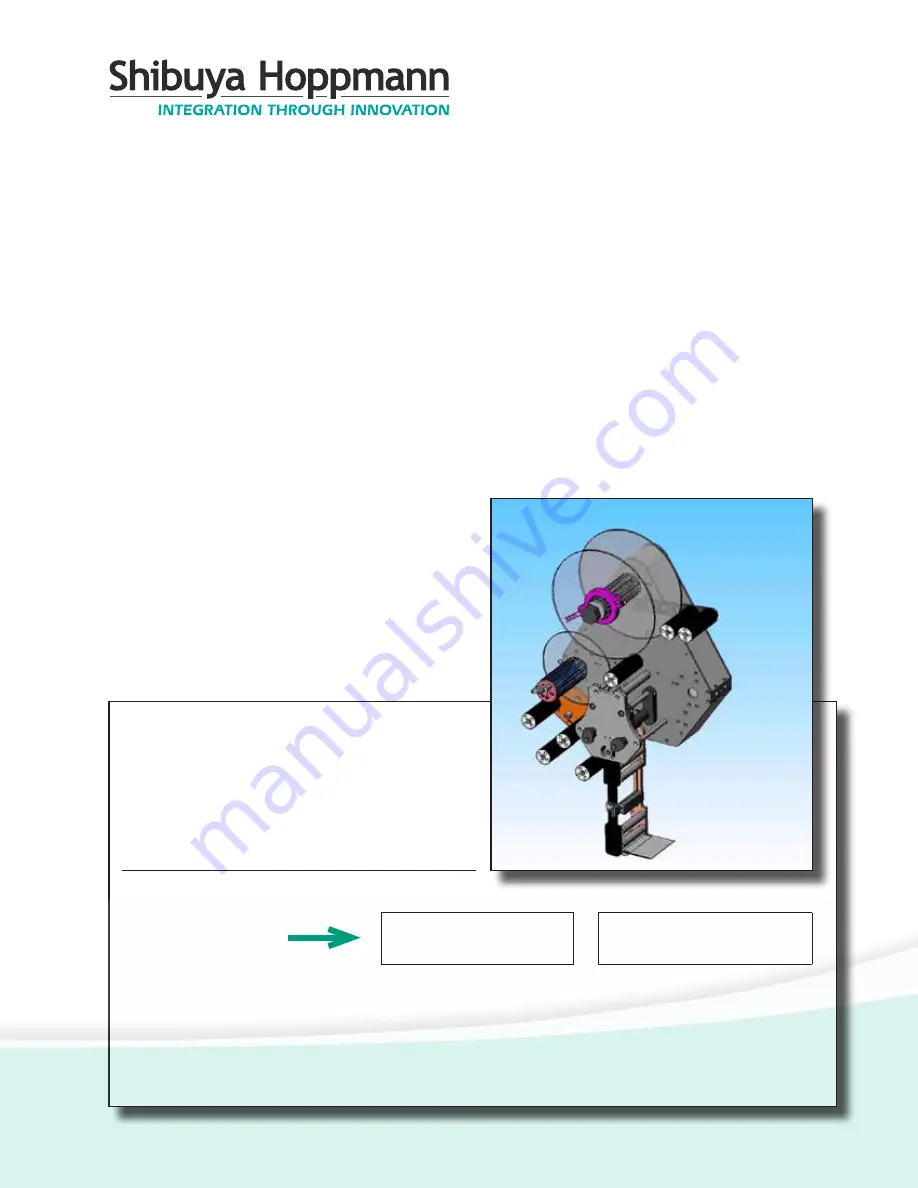
Shibuya Hoppmann L500A V2 Скачать руководство пользователя страница 1

TM

L500A V2 High

Speed Labeler

Installation/Maintenance

Manual

Publication Version, Revision 1, All rights reserved.

© 2011 Shibuya Hoppmann Corporation

13129 Airpark Drive, Suite 120 • Elkwood, Virginia 22718 • USA

Tel: (540) 829-2564 • Fax: (540) 829-1726 • E-mail:  [email protected]

Duplication of this manual, in whole or in part, requires written consent of Shibuya Hoppmann Corporation.

Model Name:

Model Inventory Number:

Refer all servicing to  qualified personnel.

This manual is intended for use by qualified

mechanic and electricians who install or service 

the L500A V2 High Speed Labeler.

Please copy this information from 

the L500A V2 High Speed Labeler’s 

serial plate.

Содержание L500A V2

Страница 1: ...9 1726 E mail publications ShibuyaHoppmann com Duplication of this manual in whole or in part requires written consent of Shibuya Hoppmann Corporation Model Name Model Inventory Number Refer all servicing to qualified personnel This manual is intended for use by qualified mechanic and electricians who install or service the L500A V2 High Speed Labeler Please copy this information from the L500A V2...

Страница 2: ... attention to and Messages hazardous voltages moving parts and other hazardous conditions The exclamation point caution symbol denotes possible personal injury and or damage to the equipment The lightning bolt caution symbol denotes possible personal injury and or damage to the equipment from electrical hazards Quick Start Equipment Improvements Shibuya Hoppmann Corporation SHC continually improve...

Страница 3: ...ning Labels Applicator Installation 15 Unpacking and Inspection 15 Applicator Positioning 20 Remote Electrical Enclosure Interface Panel 21 Power Supply Figures Tables 16 Figure 3 1 Correct Incorrect Positioning 17 Figure 3 2 Rotation Adjustment 18 Figure 3 3 U Arm 19 Figure 3 4 Adjustments for T Stand and U Arm 20 Figure 3 5 Interface Panel Applicator Setup 23 Label Threading 28 Light Tower Optio...

Страница 4: ...er Arm Assembly 39 Figure 4 14 Side Cover Removal 39 Figure 4 15 Back Panels 39 Figure 4 16 Torque Fork Assembly Hex Nut Removal 39 Figure 4 17 Torque Fork Assembly Hex Nut Locations 40 Figure 4 18 Unwind Assy Dancer Arm Assy Removal 40 Figure 4 19 Retaining Ring Shim and Shaft 41 Figure 4 20 Belt Tensioner Motor Mounting Plate 42 Figure 4 21 Rewind Flange Removal 42 Figure 4 22 Rewind Assembly Be...

Страница 5: ...Menu Wipe 69 Parameter Menu Tamp 71 Parameter Menu Blow 73 Parameter Menu Jog 74 Parameter Menu Setup 78 Diagnostics 79 Program Number Figures 51 Figure 5 1 Mapping of the Operator Interface 54 Figure 5 2 Main Screen 55 Figure 5 3 Parameter Display Screen 57 Figure 5 4 Label Auto Teach 59 Figure 5 5 Auto Center Teach Screen 60 Figure 5 6 Wipe On Mode Screen 61 Figure 5 7 Tamp On Screen 62 Figure 5...

Страница 6: ...um to which labels are applied Boxes Bottles etc Web Webbing Backing Label Strip Label Stock Label Ribbon Waste Continuous Backing Flag Before the label is completely removed from the webbing the part of label with the adhesive exposed is the flagged part of the label Labeler Applicator Chapter Page 7 Replacement Parts 85 How to Order Spare Parts 86 L500A V2 Recommended Replacement Parts List Figu...

Страница 7: ...plicator modules a Accommodatesa15 381mm supplyrolldiametertominimizedown time for reloading a Label head is converted from left hand to right hand justified without any additional parts a Gear powered label drive and torque clutch adjustable rewind a One button auto teach for fast easy repeatable changeover a Speed matching of label and product a Easy access to main components for maintenance and...

Страница 8: ...EWIND ASSEMBLY TORQUE FORK ASSEMBLY IDLER ROLLERS 4 IDLER ROLLER IDLER ROLLERS IDLER ROLLER IDLER ROLLER IDLER ROLLER HMI TOUCHSCREEN CONTROL PANEL DANCER ARM ROLLERS DANCER ARM ASSEMBLY UNWIND ASSEMBLY DRIVE ROLLER HIDDEN BY COVER PLATE NIP ROLLERS 2 HIDDEN BY COVER PLATE LABEL SENSOR ...

Страница 9: ... Labeler Chapter 1 Description and Specifications REWIND ASSEMBLY PEELER PLATE BOTTOM OF WIPER ARM HMI TOUCHSCREEN CONTROL PANEL UNWIND ASSEMBLY DRIVE ROLLER NIP ROLLER LOCKOUT CAM FOR NIP ROLLERS DRIVE MOTOR LABEL SENSOR DANCER ARM ROLLERS ...

Страница 10: ...anual 10 Figure 1 3 Different Views of the L500A V2 Labeler Back View TORQUE FORK ASSEMBLY HMI TOUCHSCREEN CONTROL PANEL UNWIND ASSEMBLY IDLER ROLLER DANCER ARM ASSEMBLY DRIVE MOTOR REWIND ASSEMBLY PEELER PLATE BOTTOM OF WIPER ARM ...

Страница 11: ...e Controls Dual processor Product Detection Photo sensor Label Sensor Capacitance Power Requirements 115 VAC 60 Hz single phase 6 Amp Shop Air For Modules Only 80 psi minimum 100 psi maximum to the filter regulator Environment 41 104 F 5 to 40 C operating temperature Relative Humidity 25 85 relative non condensing humidity Label Supply Roll 14 356mm outer diameter with 3 76mm spool inner diameter ...

Страница 12: ...L500A V2 High Speed Labeler Manual 12 Notes ...

Страница 13: ...able parts when the machine is operating Install Safety Covers Make sure the machine remains safe to operate Be sure all safety covers have been installed before operating this ma chine Safety covers include any covers installed by your direct supplier as well as the main cover and the print engine cover Each helps protect the operator from potential pinch points and moving parts Avoid Pinch Point...

Страница 14: ...L500A V2 High Speed Labeler Manual 14 Notes ...

Страница 15: ... Applicator can weigh in excess of 150 lbs 68kg Step 2 Unpack the Applicator Remove the top and sides of the shipping crate to expose the Applicator Remove the packing material Inventory the container Applicator Positioning The standard mounting procedure uses the two mounting holes that are located on each side of the applicator The optional U arm supports the applicator at those mounting locatio...

Страница 16: ...ientation Once the correct orientation is obtained the labeler is ready to be placed into position The product and labeling surface should be parallel with each other at point of contact Refer to Figure 3 1 Figure 3 1 Correct Incorrect Positioning PRODUCT PRODUCT THE TWO SURFACES SHOULD BE PARALLEL NOT PARALLEL CORRECT INCORRECT ...

Страница 17: ... from the product is suggested on the wiper arm Then rotate the peeler tip as needed Note The flag of the label is the amount of label protruding past the peeler tip Placing the peeler tip in the path of the product may cause damage to the applicator The applicator needs to be mounted in such a way that there is mini mum vibration and rotation or else the accuracy of the labeling may be compromise...

Страница 18: ... to rotate the peeler tip up or down Tighten the same nut to secure the applicator s position Refer to Figure 3 4 The applicator may also be positioned for top side or bottom panel labeling Loosen the two large socket head bolts that fasten the U arm to the labeler Rotate the applicator into a position where the application module is parallel to the surface of the product to be labeled Figure 3 3 ...

Страница 19: ...uct Refer again to Figure 3 4 To change the horizontal position of the unit simply unlock the casters on the bottom of the T stand and roll the unit to the desired location Lock the casters down once in position MOUNTING BOSS FOR OPTIONAL LEVELING FEET LOCKING CASTERS SOCKET HEAD BOLTS FOR TOP OR SIDE PANEL LABELING ADJUSTMENTS HEX NUT FOR PEELER TIP MOVEMENT CAM LOCK HANDLE FOR VERTICAL MOVEMENT ...

Страница 20: ...when connected or disconnected Encoder Plug in which an optional encoder is connected The encoder is used for synchronous mode labeling which can apply the label at the speed the product is traveling It is recommended to use an incremental encoder with at least 1024 increments LOW Label Sensor Plug in which the low label sensor is connected The low label sensor is found behind the unwind assembly ...

Страница 21: ...odules Verify Main Power The applicator is supplied with a power cord for AC operation Plug the power cord into an outlet with the proper voltage and ground Make sure the power cord is securely connected to the labeler and the outlet To test the connection turn the disconnect switch to ON see Figure 3 5 The HMI display will illuminate after approximately 30 seconds this will verify the power conne...

Страница 22: ...L500A V2 High Speed Labeler Manual 22 Notes ...

Страница 23: ...tion Thelabelsmustbewoundtotheoutside of the roll Splices Splices should be avoided as much as possible but when splices are needed please use Angle style flush to the edge and on both sides of backing using 1 25 mm cellophane splice tape Replace the label in the spliced area Label Tolerance A label tolerance of 0 05 0 02mm can be maintained provided that A Labels are manufactured to the right lab...

Страница 24: ... 9 10 12 8 11 13 14 16 15 17 18 Refer to Figure 4 1 to assist in proper label threading A label threading diagram is supplied on the front of the labeler Store label stock in a cool dry place to avoid heat damage Figure 4 1 Web Path Label Threading Path ...

Страница 25: ...he outer flange by aligning the tabs with the grooves on the extrusion see Figure 4 2 Once the outer flange is slid down over the spool along the grooves firmly seat the outer flange down over the spool and push the tabs into the core of the spool Step 3 Start to Thread the Label Stock While holding the inner flange grab and tug the label stock to make sure the roll does not slip Once secure loop ...

Страница 26: ... the nip roller position 5 and the drive shaft Figure 4 3 Lockout Knobs for Nip Rollers Step 5 Wiper Arm Thread the label stock under the first idler roller refer to position 6 and then through the second roller position 7 The label then is threaded through the label sensor position 8 and under the third idler roller position 9 then around the 4th roller position 10 The label stock over the end of...

Страница 27: ...d idler roller position 16 and finally around the last idler roller refer to position 17 Step 8 Open the Cam on the RewindAssembly Open the cam refer to Figure 4 4 on the extrusion shaft of the rewind assembly Insert a portion of the end of the label into the cam and rotate the wheel to wrap up excess label stock The label stock media should be riding evenly on the rollers and the tension should b...

Страница 28: ...el path through the labeler Once the label stock is properly positioned jog the labeler at low speed to position the label on the peeler plate appropriately Step 11 Using Label Teach in the Control Screens Once the label is correctly situated on the peeler plate go to the Label Teach screen and press EN TER This allows the labeler to learn the label position The labeler should dispense three label...

Страница 29: ...l and illuminates the amber light on the light tower refer Figure 4 5 This sensor is hard wired to terminals in the electrical enclosure see Appendix for details Chapter 4 Applicator Setup Light Tower Optional The optional light tower refer to Figure 4 5 can be connected to the labeler to indicate different conditions of the labeler at any given time Figure 4 6 Low Label Sensor Figure 4 5 Light To...

Страница 30: ...embly To decrease feed rate turn the nut counterclockwise which applies less friction to the friction washer see Figure 4 7 As the rewind assembly fills the rewinding speed may become too slow This is due to the increased weight of web waste on the rewind assembly To prevent a slowdown from occurring adjust the rewind speed as if the rewind assembly was full Initially the rewind assembly may exert...

Страница 31: ...al to the performance of the sensor see Figure 4 8 Excessive vibration may cause false read ings Anything behind the product that could cause a false sensor reading should be moved or placed as far away as possible Figure 4 8 Product Sensor Setup PARAMETER 0 to detect rising product sensor signal edge Sensor output signal to 24V if sensor detects a product Sensor output signal to 0V or open output...

Страница 32: ...perate will drastically affect the operation of the applicator and any modules being used Once the sensor is mounted and the product is in place apply power and advance the GAIN control to maximum clockwise rotation If the sensor is seeing its reflected light the sensor alignment red LED Figure 4 9 Product Sensor Setup Gain THIS IS A 15 TURN CLUTCHED POTENTIOMETER TURN CLOCKWISE TO INCREASE GAIN T...

Страница 33: ...the following alternatives Move the sensor closer to the object and reduce the sensitivity GAIN Reduce background reflectiveness by painting the background with flat black paint scuffing the background or cutting a hole in it Tilt the sensor or the background so that the sensing beam is not perpendicular to the background Lion LRD 2100 Label Sensor Overview The Lion LRD 2100C Label Sensor is an el...

Страница 34: ...or Step 2 Gain Adjust Center GAIN ADJUST see Figure 4 10 Turn GAIN ADJUSTfour 4 turns counter clockwise then turn GAINADJUSTtwo 2 turns clockwise Figure 4 10 Retroreflective Mode Alignment G A IN A D J U S T Z E R O A D J U S T 4X GAIN ADJUST ZERO ADJUST Step 3 Zero Adjust Set ZERO ADJUST to the point where the ZERO light just begins to come on It is not important if the light is on or off what is...

Страница 35: ... I O N Setting the Labeling System Usually a labeling system is set up for dispensing a maximum number of labels at a maximum speed with shortest acceleration and deceleration times and distances See Chapter 5 for details There are different ways to set up a labeling system To achieve maximum performance use the following method Step 1 Select Spool Size Use the largest spool with the largest label...

Страница 36: ...e On Screen step by step and find out at which point the stepping motor stalls If the motor stalls reduce the maximum speed back to a safe rating Note This value can be adjusted in the Wipe On Screen See Chapter 5 Step 6 DecreaseAcceleration DecelerationRamp Continuedispensinglabels Now decrease the Acceleration Deceleration Ramp step by step starting from the default 50 ms If the motor stalls inc...

Страница 37: ...ent Overview This is a shortened list of steps to complete changeover Use the pro cedures on the following pages for complete changeover from Right Hand to Left Hand label applications a Turn off Labeler Use Disconnect Switch a Disconnect External Cables a Remove Wiper Arm Assembly a Remove Side Covers a Remove Torque Fork Assembly a Remove Wiper Arm Assembly a Remove Back Panel a Remove the Rewin...

Страница 38: ... shaft upward through the opening on the top of the face plate so the wiper arm is freed the arm may need to be jiggled to ease pressure on the pivot shaft Once removed slide the pivot shaft up and out of the hole see Figure 4 12 Using both hands slide the wiper arm out and set aside see Figure 4 13 Step 3 Remove all the covers on the side and bottom by removing the four 4 bolts on each cover usin...

Страница 39: ...e 4 16 and 4 17 Set the assembly aside Figure 4 14 Side Cover Removal Figure 4 15 Side Cover Removal DRIVE MOTOR BACK PLATES STAINLESS STEEL Figure 4 17 Torque Fork Assembly Hex Nuts Locations REWIND ASSEMBLY WHEEL TORQUE FORK ASSEMBLY HEX NUT SCREWS Figure 4 16 Torque Fork Assembly Hex Nuts REWIND ASSEMBLY TORQUE FORK ASSEMBLY REMOVE THESE TWO 2 HEX NUTS ...

Страница 40: ... aside Figure 4 19 Retaining Ring Shim and Shaft RETAINING RING SHIM SHAFT 4 18 Unwind Assembly and Dancer Arm Assembly Shaft Removal DANCER ARM ASSEMBLY SHAFT W RETAINING RING UNWIND ASSEMBLY SHAFT BACK PANEL Step 7 Relieve the drive belt tension by loosening the tensioner s jam nut see Figure 4 20 and then the tensioner bolt Loosen but do not remove the two 2 socket head cap screws that holds th...

Страница 41: ...lock to the flip other side of the motor assembly plate where the mark has been made from Step 10 The two mounting holes the slot and the notch on the block will line up on the assembly plate Finger tighten the idler pulley Step 14 Reinstall the motor to the motor mounting plate Ensure the motor cable is facing towards the outside of the machine opposite of the previous location 4 20 Belt Tensione...

Страница 42: ... DRIVE BELT REWIND ASSEMBLY BEARING PLATE STANDOFF Step 16 On the back of the labeler remove the retaining ring and any associ ated shim from the Rewind Shaft Remove also the retaining ring and any associated shim from the front of the labeler see Figure 4 22 If shims are used make sure you bag and tag the retaining rings and the shims marking their original location and that they are used when re...

Страница 43: ...ndoffs need to be re located The manufacturer has preinstalled the other one see Figure 4 24 REWIND CLUTCH ASSEMBLY FRONT COVER TO BACK COVER SIDE STANDOFF 4 23 Side Standoff Locations Step 20 Remove and reinstall the two 2 Rewind Assembly Clutch standoffs to the other side 4 24 Standoff Relocation from One Side to the Other REWIND CLUTCH ASSEMBLY REWIND ASSEMBLY BEARING PLATE STANDOFFS MOTOR MOUN...

Страница 44: ...w location on the opposite side of the labeler see Figure 4 25 4 25 Rewind Clutch Assembly Installation 4 26 Drive Belt Threaded for Left Hand Running MOTOR GEAR DRIVE GEAR REWIND CLUTCH ASSEMBLY IDLER PULLEY Step 23 Reinstall the retaining ring on the front side of the labeler over the Rewind Shaft Step 24 Hang the drive belt around the drive gear and the newly installed Rewind Clutch As sembly g...

Страница 45: ...ve roller gear in that order There is plenty of finger room to route the belt properly Check that the belt runs true making any adjustments as necessary Step 30 Retension the belt and tighten the jam nut Do not over tighten The pul ley should be halfway or just beyond halfway of the slot s full travel A deflection of 1 8 when checked half way between the drive gear and the rewind gear is acceptabl...

Страница 46: ...ove the socket head cap screw at the dancer arm shaft and remove the dancer arm The dancer arm s socket head cap screw was set using removable Loctite 242 Step 35 Relocate the dancer arm bumper s to the other side of the front plate refer to Figure 4 29 Figure 4 28 Unwind Flange Shaft Key BRAKE BELT UNWIND FLANGE SHAFT KEY FRONT OF LABELER DANCER ARM Figure 4 29 Dancer Arm Bumpers on Front of Labe...

Страница 47: ...control arm holding the Dancer Arm Spring shaft in place and pull the shaft out of the con trol arm Flip it over to the other side and retighten the screw See Figure 4 31 and Figure 4 32 Step 39 Reinstall the Dancer Arm Shaft cam but do not yet tighten Figure 4 30 Reversing the Brake Control Arm BRAKE BELT CAM LOOSEN SETSCREW AND REMOVE CAM CONTROL ARM DANCER ARM SHAFT Figure 4 31 Removing the Bra...

Страница 48: ... lob is at the 1 00 o clock po sition when in contact with the micro switch lever Step 44 Set the Dancer Arm Limits Note To adjust for the maximum adjustment and travel pull the dancer arm down to the bottom rubber stop rotate the cam until the electric brake disengages Release the dancer arm and rotate the cam in the op posite direction until the brake comes on Step 45 Turn the labeler back into ...

Страница 49: ... Direction value Toggle to the MOTOR DIRECTION screen and change the current setting to the appropriate configuration A setting of 0 is needed for a clockwise CW rotation positive of the motor shaft looking on top of the motor or right hand application and a set ting of 1 is needed for a counterclockwise CCW rotation negative of the motor shaft looking at the top of the motor shaft or left hand ap...

Страница 50: ...L500A V2 High Speed Labeler Manual 50 Notes ...

Страница 51: ...PE ON ASYNCHRONOUS SYNCHRONOUS JOG LABEL TEACH AUTO CENTER AUTO CENTER TEACH START AUTO CENTER OFF AUTO CENTER ON TAMP ON STOP BLOW ON STOP TAMP BLOW STOP START DELAY STOP DISTANCE COMPENSATION SPEED START COMPENSATION STOP COMPENSATION ASYNCHRONOUS SPEED ACCEL DECEL RAMP AUTO CENTER FREE TIMER IMPRINTER RATIO ADJUST PARAMETER WIPE PARAMETER PASSWORD START STOP ...

Страница 52: ... AIR ASSIST DWELL PARAMETER BLOW PARAMETER TAMP LOW SPEED HIGH SPEED ACCEL DECEL RAMP PARAMETER JOG GEAR NUMERATOR GEAR DENOMINATOR LABEL PITCH CURRENT REDUCTION PRODUCT SENSOR EDGE LABEL SENSOR EDGE MOTOR DIRECTION PASSWORD PRODUCTS TO SKIP MAX MISSING LABELS AUTO WEB ADVANCE WEB ADVANCE SPEED TIMER 1 PARAMETER SETUP PARAMETER Continued on From Previous Page PROGRAM NUMBER SELECT PROGRAM NUMBER D...

Страница 53: ...ator should take time to sample various settings and observe how they affect the performance of the labeler Operating Mode The two operating modes available are synchronous and asynchronous The operator may change between modes by simply selecting the appo priate mode in the WIPE ON screen When synchronous mode is chosen the labeler will dispense labels at the speed determined by the encoder data ...

Страница 54: ...le after thirty 30 seconds Choose the operating function JOG LABEL TEACH etc in order to set up the parameters for the different operating modes refer to Figure 5 2 Figure 5 2 Main Screen BLS 2020 M188 SCRUP SCRDN ENTER JOG LABEL TEACH AUTO CENTER Scroll up in main menu Press enter select desired mode Scroll down in menu Operating Mode Highlighted is currently selected Operational Modes Jog Label ...

Страница 55: ... Parameter Name Parameter Value Parameter Group Parameter Unit Parameter Display Scroll down in menu Increase Digit Value Store Value and Exit Shift to Left Decrease Digit Value Shift to Right Key Assignment of Parameter Menu lets the operator change the values on the parameter screen for that parameter Key Assignment of Parameter Display Menu shows the established values on the parameter screen f...

Страница 56: ...lays the amount of steps that the motor has moved in positive direction after the JOG mode was started The counter will be reset when the JOG mode is restarted Operational Modes Label Auto Teach This function is used to determine the length of a label pitch and the stop distances used for the labeling process It begins when START is pressed The speed for the Label Teach mode is the low jog speed S...

Страница 57: ...ain menu The function advances the web 3 4 label lengths with the manual low speed WiththedigitalinputLABEL_SENSatotalof3labellengths including the gaps between the labels are measured and the average length of the 3 label lengths is then calculated as a set value LABEL PITCH then later used in the actual labeling operations Problems with the adjustment of the label sensor or with label web itself...

Страница 58: ...nous a The following steps are followed 1 SwitchcontrollertoWIPE ONmodeandsynchronousdispensing mode first and make that AUTO CENTER function switched of In case the AUTO Center icon is displayed switch the AUTO CENTER function off first 2 Start dispensing labels at low speed and by using the START DELAY parameter adjust the label position on the product so that the leading edge of the label is fl...

Страница 59: ...rquired exit at this point 7 SwitchAUTO CENTER on by pressing the corresponding menu keyonthescreen Asymbolappearsinthelowerleftscreencorner to indicate that AUTO CENTER is ON The AUTO CENTER symbol is also displayed in the WIPE ON function screen Chapter 5 Operator Interface Figure 5 5 Auto Center Teach Screen BLS 2020 M188 MENU START ON AUTO CENTER TEACH OFF _ _ _ _ 12345 X AUTO CENTER symbol in...

Страница 60: ... dispensing mode Both modes can be used to dispense labels up to a high speed range While WIPE ON mode is running The DELAY and the SPEED can be adjustedwiththeM188terminal TheENTERkeytogglesbetweenSPEED and DELAYadjust In asynchronous dispensing mode theASYNCHRO NOUS SPEED is adjusted by increasing the speed 1 or 1 of the previously set value In synchronous dispensing mode the gear RATIO ADJUST i...

Страница 61: ...is recommended to set the delay in the parameter menu first as close as possible to the desired position Especially when there is a high encoder line count the change of the label position on the product is minimal for a single encoder increment and it will take a long time to adjust the label position Operational Modes Tamp On Blow On and Tamp Blow Using the main screen different operating modes ...

Страница 62: ... password accepted and move on to the Parameter Group Screen Parameter Group Screen The Parameter Group Screens allows the operator to select the group parameter todisplayoredit Theup downarrowfunctionbuttons qp allow the operator to move up and down the list to choose the parameter The choices are a Parameter Wipe a Parameter Tamp a Parameter Blow a Parameter Jog a Parameter Setup a Diagnostics a...

Страница 63: ...ler tip Increase value to position label closer to trailing edge of product Decrease value to position label closer to leading edge of product The value is based on the Encoder setup Need to calculate encoder resolution mm increments based on setup see example under Encoder Setup page and then value input is multiplied by encoder resolution to obtain distance in millimeters a Min Value 0 Increm Ma...

Страница 64: ...9999 steps a Default setting 100 a Setting is retained when power is turned off Lead Initiates timing on the leading edge of the product Trail Initiates timing on the trailing edge of the product COMPENSATION SPEED The Compensation Speed parameter defines the maximum motor speed for the synchronous dispensing operation a Min Value 1 Hz Max Value 99999 Hz a Default setting 10000 The default value s...

Страница 65: ...ighest labeling speed you want to reach with your labeling head Step 3 Measure the offset distance between the two variations in encoder incre ments Step 4 Use the highest labeling speed used as the compensation speed and the amount of steps as a positive start compensation distance value Enter this value into the screen Step 5 This compensation needs to be done only once since it is a fixed machi...

Страница 66: ...ur label head Step 3 Determine the offset distance in motor steps Knowing the mechanical parameters and gear factors of the labeling head make it possible to cal culate the amount of steps the label is off at high speeds Step 4 Use the highest labeling speed as the compensation speed and the amount of steps as a stop compensation distance value Enter this value into the screen Step 5 This compensa...

Страница 67: ...1000 Note Screen input is only relevant in the ASYNCHRONOUS mode It cannot exceed the maximum speed of the labeler The asynchronous speed value Hz is dependent on the motor resolution setting See examples below ASYNCHRONOUS SPEED 1000 Hz PARAMETER WIPE EXIT ENTER SCRUP SCRDN ACCEL DECEL RAMP 50 ms PARAMETER WIPE EXIT ENTER SCRUP SCRDN 25 4mm 1 in 12 in ft 100ft min 1 min 60 sec STEP 1mm 5080 Hz DE...

Страница 68: ...vates the TIMER_T1 output The smaller value less time for the motor to reach speed The larger value more time to reach maximum speed a Min Value 1 ms Max Value 1000 ms a Default value 50 Note See WIPE ON timing chart for more information IMPRINTER The Imprinter timer is started in Wipe On mode when the label cycle is completed It can be used to trigger peripheral equipment counters etc a Min Value...

Страница 69: ...duct and activation of tamp assem bly Larger number to position label closer to trailing edge of product Smaller number to position label closer to leading edge of product a Min Value 0 ms Max Value 99999 ms a Default value 0 TAMP DWELL Sets dwell time for the tamp assembly Larger number to extend the time the tamp is extended Smaller number to reduce the time the tamp is extended a Min Value 0 ms...

Страница 70: ...ime aIf the leading edge of the label does not arrive all the way to the edge of the tamp increase this setting aMin Value 0 ms Max Value 99999 ms aDefault value 100 AIR ASSIST DELAY Used to smooth the transition of the label from the peeler tip to the tamp pad See also Vacuum Delay screen Larger number to turn the air assist valve on later Smaller number to turn the air assist valve on earlier aD...

Страница 71: ... number to position label closer to trailing edge of product Smaller number to position label closer to leading edge of product a Min Value 0 ms Max Value 99999 ms a Default value 0 BLOW DWELL Sets dwell time for the blow assembly Larger number to extend the time the blow assembly is activated Smaller number to reduce the time the blow assembly is activated aWhenablowassemblyisinstalled VacuumDwel...

Страница 72: ... applying the label Larger number to keep the vacuum activated for more time Smaller number to keep the vacuum activated for less time a Min Value 0 ms Max Value 99999 ms a Default value 0 AIR ASSIST DELAY Used to smooth the transition of the label from the peeler tip to the blow assembly See also Vacuum Delay screen Larger number to turn the air assist valve on later Smaller number to turn the ai...

Страница 73: ...ue 1 Hz Max Value 20000 Hz a Default value 100 HIGH SPEED Sets the high speed in the jog mode a Min Value 1 Hz Max Value 20000 Hz a Default value 1000 ACCEL DECEL SPEED Acceleration Deceleration speed is the time the motor takes to obtain reach jog speed The smaller value less time for the motor to reach speed The larger value more time to reach maximum speed a Min Value 1 ms Max Value 1000 ms a D...

Страница 74: ...eed When using a non manufacturer supplied encoder refer to page 56 of this manual completing steps 1 6 Step 6 equals the denominator value Note Do not use step 7 To calculate required value for a certain dispense speed see example below UP DOWN DIGIT GEAR NUMERATOR 00000 select PARAMETER SETUP DIGIT ENTER UP DOWN DIGIT GEAR DENOMINATOR 00000 select PARAMETER SETUP DIGIT ENTER DP220 DP80 DP100 DP2...

Страница 75: ...mended that this value not be changed a Min Value 0 select Max Value 255 select a Default value 255 PRODUCT SENSOR EDGE Toggles between Lead and Trail detection on the product sensor 1 Trail 0 Lead Default Lead Initiates timing on the leading edge of the product Trail Initiates timing on the trailing edge of the product Note Settings valid if product sensor is set to light operated mode a Min Valu...

Страница 76: ... Min Value 0 select Max Value 1 select a Default value 0 PASSWORD Sets the password for the parameter menu access Allows the operator to change the password a Min Value 0 select Max Value 99999 select a Default value 0 PRODUCTS TO SKIP Allows the labeler to be programmed to skip or pass over a set number of products that should not be labeled a Min Value 0 select Max Value 99999 select a Default v...

Страница 77: ... Max Value 99999 select a Default value 0 AUTO WEB ADVANCE Sets the number of labels from the peeler plate to the sensor not includ ing the label sensed so that when a missing label is detected the web will advance the correct distance quickly and no product is skipped or missing a label a Min Value 0 select Max Value 16 select a Default value 0 MAX MISSING LABELS 00000 select PARAMETER SETUP EXIT...

Страница 78: ... Value 0 ms Max Value 10000 Hz a Default value 0 Diagnostics Diagnostics The diagnostics function can be used tocheckthefunctionofallthesensors in the labeling system label sensor product sensor incremental encoder inadditiontodisplayingthelabelcycle count see Figure 5 9 To activate the diagnostics mode switch to the Parameter menu then select DIAGNOSTICS and press enter Figure 5 9 Diagnostics Scr...

Страница 79: ...Cycle Count The controller counts all labeling cycles and writes the number to a retain memory location This information can be helpful to determine the use of the labeling machine e g for warranty or maintenance information The user cannot reset the label cycle count only by reloading the labeling software program the counter can be reset Program Number PROGRAM NUMBER The C229 controller can stor...

Страница 80: ...L500A V2 High Speed Labeler Manual 80 Notes ...

Страница 81: ...on may be used to clean problem areas Do not use compressed air to blow dust from the labeler a Inspect all electrical plugs for secure connections a Verify that all components and modules are securely fastened a Inspect the unit for loose screws guides or covers and tighten as necessary a Gently clean dust from the lens of the product sensor a Inspect the drive belt for proper tension Adjust idle...

Страница 82: ...or power am plifier short circuit between two motor phases or between motor phase against PE over voltage low voltage rotation monitoring RM fault power amplifier deactivation or motor current free Refer to the LED status display of the stepper motor drive inside the electrical cabinet see Figure 6 1 Figure 6 1 Stepper Drive Motor Fault Display Labeling Errors Labeling errors can be caused by miss...

Страница 83: ...the peeler plate Step 4 Release JOG button to stop web at desired position If the motor is rotating in the wrong direction you will need to follow the steps below to correct Solution 1 The hardware solution If using a 3 phase BERGER LAHR stepping motor system interchange two motor wires only at shut down system with no mains power connected For other systems refer to the manual Some of the drives ...

Страница 84: ...L500A V2 High Speed Labeler Manual 84 Notes ...

Страница 85: ...ay order your system s spare parts directly from Shibuya Hopp mann by email phone or FAX at the numbers listed below Or contact our Spare Parts Coordinator at our address Email spares ShibuyaHoppmann com Telephone 540 829 2564 Fax 540 829 1726 Shibuya Hoppmann Corporation Attn Spare Parts Coordinator 13129 Airpark Drive Suite 120 Elkwood Virginia 22718 USA www shibuyahoppmann com 7 ...

Страница 86: ...rco Switch L030410501 Sensor Lion L050601334 Brake Belt High Speed 19 L020800509 Spring Collar 2 80688 Spring 1 2 OD 1 75 L 049 Wire dia 9540K16 Rubber Bumper 21 32 dia x 1 2 t L050602008 Inner Unwind Flange L050602009 Outer Unwind Flange BRNG000036 Bearing 3 8 ID x 1 1 8 OD KNOB000039 Knob L050600049 Locking Collar Assy FAN24VDC01 Fan 24VDC L030300100 Power Supply 24VDC 2 4A PLUG040410 Panel Moun...

Страница 87: ...ead 4 Format 1 2 MH0202830 Roller Sponge Head Head 2 3 Format 1 2 MH0202831 Roller Sponge Head Head 2 3 Format 3 4 MH0202832 Roller Sponge Head 4 Format 1 2 L500A V2 6 Head Spares Head 1 Part Number Description MH0202825 Peeler Plate Head 1 Format 1 2 MH0202829 Roller Sponge Head 1 Format 1 2 L500A V2 6 Head Spares Part Number Description L050601332 1 Idler Peeler Arm 6 Head L050400906 Nip Frictio...

Страница 88: ...L500A V2 High Speed Labeler Manual 88 L500A V2 Labeler Callouts Figure 7 2 L500A V2 Labeler Front and Side Views Callouts ...

Страница 89: ...89 Appendix Figure 8 1 Wiring Diagram 8 ...

Страница 90: ...L500A V2 High Speed Labeler Manual 90 Figure 8 2 Wiring Diagram ...

Страница 91: ... Corporation but a part of the system is limited to the warranty provided by the original manufacturer of said components to the extent and only to the extent that such original manufacturer actually honors such war ranty ALL WARRANTIES HEREUNDER ARE EXPRESSLY LIMITED TO THE REPAIR OR REPLACEMENT OF DEFECTIVE ITEMS AS SET FORTH HEREIN AND IN NO EVENT SHALL SHIBUYA HOPP MANN CORPORATION BE LIABLE F...

Страница 92: ...gal Feeders Ü Prefeeders Ü Continuous Motion Assembly Turrets Ü Placement Systems Ü Fillers and Cappers Ü Conveyors Headquarters Sales Office Manufacturing Office 13129 Airpark Drive 1445 Brookville Way 281 Dillard Road Suite 120 Suite F Madison Heights VA Elkwood VA 22718 Indianapolis IN 46239 24572 540 829 2564 t 317 322 0754 t 434 929 4746 t 800 368 3582 t 800 368 3582 t 800 543 0915 t 540 829 ...

Отзывы: