background image

PN-K321/K322B  INSTALLATION, ADJUSTMENT, SETTING  2 - 9 


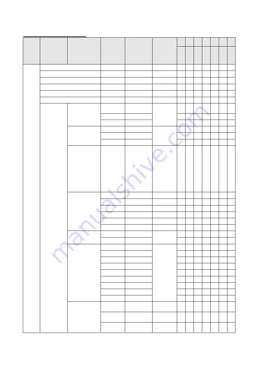
2 – 2.ADJUSTMENT ITEM LIST 

ITEM 

DETAIL 1 

DETAIL 2 

ALTANATIVE

ADJUSTMENT

DEFAULT 

VALUE 

PC


AV
 

AV
 

PC


PC


AV
 

PC


Disp

la

y

P

o

rt


HDMI1


HDMI2


HDMI1


HDMI2


HDMI DUA

L


HDMI DUA

L


PICTUER BRIGHT


Value 

0 to 31 

31 

● 

● 

● 

● 


CONTRAST


Value 

0 to 60 

30 

● 

● 

● 

● 


BLACKLEVEL


Value 

0 to 60 

30 

● 

● 

● 

● 


TINT


Value 

0 to 60 

30 

● 

● 

● 

● 


COLORS


Value 

0 to 60 

30 

● 

● 

● 

● 


SHARPNESS


Value 

0 to 24 

12 

● 

● 

● 

● 


COLORADJUS 

TMENT


COLOR MODE


STD 


STD 

● 

● 

● 

● 


VIVID 


● 

● 

● 

● 


sRGB 


● 

● 

● 

● 


 WHITE 

BALANCE 

THRU 


PRESET 

● 

● 

-


PRESET 


● 

● 

● 

● 


USER 


● 

● 

● 

● 


PRESET


Value 

3000, 3200, 3500, 

4000, 4500, 5000, 

5500, 5600, 6000, 

6500, 7000, 7500, 

8000, 8500, 9000, 

9300, 9500, 10000

6500 

● 

● 

● 

● 


USER


Value 

0 to 256 

256 

● 

● 

● 

● 


Value 

0 to 256 

256 

● 

● 

● 

● 


Value 

0 to 256 

256 

● 

● 

● 

● 


Value -127 

to 

+127 

● 

● 

● 

● 


Value -127 

to 

+127 

● 

● 

● 

● 


Value -127 

to 

+127 

● 

● 

● 

● 


COPY TO USER


OFF 


OFF 

● 

● 

● 

● 


ON 


● 

● 

● 

● 


GAMMA


LIGHT 2 


STD(AV,PC) 

-

● 

● 

-

-


LIGHT 1 


-

● 

● 

-

-


STD 


● 

● 

● 

● 


DARK 


-

● 

● 

-

-


1.8 


● 

● 

-


2.2 


● 

● 

-


2.4 


● 

● 

-


OPTION 


● 

● 

-


2.0 


● 

● 

-


C.M.S.-HUE


-10 to 0 to +10 

-

● 

● 

-

-


-10 to 0 to +10 

-

● 

● 

-

-


-10 to 0 to +10 

-

● 

● 

-

-

Содержание PN-K321

Страница 1: ...CEDURES 4 1 CHAPTER 5 FIRMWARE UPDATE PROCEDURES 5 1 CHAPTER 6 DISASSEMBLY AND ASSEMBLY 6 1 CHAPTER 7 TOROUBLESHOOTING 7 1 CHAPTER 8 HARDWARE DESVCRIPTIONS 8 1 SHARP CORPORATION CONTENT This document has been published to be used for after sales service only The contents are subject to change without notice Parts marked with are important for maintaining the safety of the set Be sure to replace th...

Страница 2: ...th the PWB for longer time This may cause land separation or may exceed the heat resistive temperature of components Use enough care to separate the soldering iron from the PWB when completion of soldering is confirmed Since lead free solder includes a greater quantity of tin the iron tip may corrode easily Turn ON OFF the soldering iron power frequently If different kind solder remains on the sol...

Страница 3: ...ut signal waiting mode standby mode 93W dedicated AC adapter is used 87W body 19 5V input 97W dedicated AC adapter is used 91W body 19 5V input Dimensions excluding protrusions inch mm Approx 29 17 32 W x 1 25 64 D x 17 3 8 H 750 x 35 x 441 monitor only Approx 29 17 32 W x 10 3 32 D x 19 17 64 24 31 32 H 750 x 256 x 489 634 monitor on supplied stand Monitor only Approx 29 17 32 W x 1 27 64 D x 17 ...

Страница 4: ...ounting method SHARP recommends using M6 screws and tighten the screws Note that screw hole depth of the monitor is 3 8 inch 10 mm Loose mounting may cause the product to fall resulting in serious personal injuries as well as damage to the product The screw and hole should come together with over 5 16 inch 8 mm length of thread Use a bracket which has been approved for UL1678 standard and which ca...

Страница 5: ... M6 screws and tighten the screws Note that screw hole depth of the monitor is 3 8 inch 10 mm Loose mounting may cause the product to fall resulting in serious personal injuries as well as damage to the product The screw and hole should come together with over 5 16 inch 8 mm length of thread Use a bracket which has been approved for UL1678 standard and which can endure at least 4 times or more the...

Страница 6: ...ut of two systems using HDMI1 and HDMI2 2 Displays a reduced image except in Dot by Dot In Dot by Dot the image will be cut down to panel size then displayed 3 Displays using multi streaming 4 The two HDMI input terminals both have 1920 x 2160 signals 5 The two HDMI input terminals both have 2048 x 2160 signals 6 The signals for the left and right screens are both 1920 x 2160 signals All are compl...

Страница 7: ...gement This monitor conforms to VESA DisplayPort power management 1 6 DDC plug and play The monitor supports the VESA DDC Display Data Channel standard DDC is a signal standard for plug and play between monitors and computers Information about resolution and other parameters is exchanged between the two This function can be used if the computer supports DDC and it has been configured to detect plu...

Страница 8: ...ntal sticker Operation buttons 1 Cover Sharp logo 1 Place this sticker onto the SHARP logo to cover the logo PN K322B Liquid Crystal Display Monitor 1 Touch pen 1 Cable cover 1 Power cord 1 About 2m AC adapter 1 CD ROM Utility Disk for Windows 1 Setup Manual 1 DisplayPort cable 1 About 2m RS 232C conversion cable Φ3 5 mini jack 1 USB cable for touch panel miniB 1 Cable clamp 2 Cable clamp small 1 ...

Страница 9: ...nLane 2 16 Gnd 7 MainLane 1 17 Aux 8 Gnd 18 Hot plug detection 9 MainLane 1 19 Gnd 10 MainLane 0 20 3 3V PC AV HDMI input terminal pins HDMI TM Connector No Function No Function 1 TMDS data 2 11 TMDS clock shield 2 TMDS data 2 shield 12 TMDS clock 3 TMDS data 2 13 CEC 4 TMDS data 1 14 N C 5 TMDS data 1 shield 15 SCL 6 TMDS data 1 16 SDA 7 TMDS data 0 17 DDC CEC GND 8 TMDS data 0 shield 18 5V 9 TMD...

Страница 10: ... power switch or the POWER button off and back on always wait for at least 5 seconds A short interval may result in a malfunction Rear view 1 Speakers 11 Main power switch 2 Vents 12 Antitheft hole 3 Attachment plate 13 Power button 4 RS 232C input terminal 14 Brightness adjustment button 5 PC AV HDMI 1 input terminal 15 Brightness adjustment button 6 PC AV HDMI 2 input terminal 16 VOL button 7 Di...

Страница 11: ...al 14 Power button 5 PC AV HDMI 1 input terminal 15 Brightness adjustment button 6 PC AV HDMI 2 input terminal 16 Brightness adjustment button 7 DisplayPort input terminal 17 VOL button 8 Audio input terminal 18 VOL button 9 USB mini B port 19 MENU ENTER button 10 Headphone terminal 20 INPUT RETURN button 21 USB terminal for service Lighting Status Status Description Green lit Power on Off lit Pow...

Страница 12: ... when you display the images of the computer screen and television VCR simultaneously for profit making or to show the image to the public The screen size for dual screen display is the same as the screen size for single screen display The Dot by Dot screen is displayed in NORMAL size When dual screen display is selected the SCREEN MOTION function is disabled When dual screen display is selected t...

Страница 13: ...wing in establishments like cafes or hotels may infringe on the rights of the creators as protected by Copyright Law so please be careful When dual screen display is selected the screen size cannot be changed The appearance of the original video may change if you select a screen size with a different aspect ratio than the original image e g TV broadcast or video input from external equipment When ...

Страница 14: ...sed by improper mounting or mishandling Use the monitor with the surface perpendicular to a level surface If necessary the monitor may be tilted up to 25 degrees upward or 20 degrees downward This monitor should be used at an ambient temperature between 32 F 0 C and 104 F 40 C Provide enough space around the monitor to prevent heat from accumulating inside When you install this monitor on a wall t...

Страница 15: ...h any other devices 1 Spread a thick soft cloth blanket etc that will prevent damage to the LCD panel on a stable flat surface where the entire monitor can be placed and place the monitor with the LCD panel face down on the cloth 2 Remove the screws x4 that fasten the attachment plate and remove the attachment plate Toppling prevention Caution To reduce the risk of injury and damage caused by the ...

Страница 16: ...C 2 PC AV HDMI1 input terminal Use a commercially available HDMI cable Ver 1 4a compatible High Speed cable compliant Set HDMI1 HDMI2 or HDMI DUAL in INPUT SELECT on the SETUP menu according to the device to be connected Please select the audio input terminal to be used in the Settings menu of the Audio Settings HDMI1 AV HDMI1 PC HDMI2 AV and HDMI2 PC For HDMI connect to the audio input terminal i...

Страница 17: ... adapter supplied to the AC input terminal 4 Plug of the power cord supplied into the AC power outlet MEMO Be sure to clamp the AC adapter cable supplied onto the cable clamp attachment using the supplied cable clamp When clamping the AC adapter cable take care not to stress the terminal of the AC adapter cable Do not bend the AC adapter cable excessively Landscape Portrait Caution Do not fasten t...

Страница 18: ...stened with the cable clamp Attach the cable clamps to the attachment parts on the back of the monitor and the stand and bind the cables Storing the cables The cables connected to the rear of the monitor can be bound using the cable clamp on the stand Landscape Portrait Caution Do not forcibly bend or apply force to the cables Risk of wire breakage or other damage ...

Страница 19: ...d fasten to the stand strut with the supplied countersunk screws M4 x 6 without washers x5 Use the supplied hex wrench 3 Spread a thick soft cloth blanket etc that will prevent damage to the LCD panel on a stable flat surface where the entire monitor can be placed and place the monitor with the LCD panel face down on the cloth 4 Place the stand on the monitor Hook the tab on the stand under the mo...

Страница 20: ...tons are located on the top side Set the MONITOR on the MONITOR menu to PORTRAIT Height Angle adjustment Adjusting the height Adjust to a height that is easy to view The height cannot be adjusted in a vertical installation Adjusting the angle Adjust to an angle that is easy to view Caution When moving the monitor be sure to grasp only the frame Grasping and applying pressure to the LCD panel may d...

Страница 21: ...press any buttons for about 4 seconds the VOLUME menu automatically disappears Move the cursor up or down in the menu screen and increase or decrease the setting The cursor moves up when the VOL button is pressed and down when the VOL button is pressed 6 MENU ENTER button Displays and turns off the menu screen Settings can be entered when the menu screen is displayed 7 INPUT RETURN button The inpu...

Страница 22: ...30 COLORS Value 0 to 60 30 SHARPNESS Value 0 to 24 12 COLORADJUS TMENT COLOR MODE STD STD VIVID sRGB WHITE BALANCE THRU PRESET PRESET USER PRESET Value 3000 3200 3500 4000 4500 5000 5500 5600 6000 6500 7000 7500 8000 8500 9000 9300 9500 10000 6500 USER Value 0 to 256 256 Value 0 to 256 256 Value 0 to 256 256 Value 127 to 127 0 Value 127 to 127 0 Value 127 to 127 0 COPY TO USER OFF OFF ON GAMMA LIG...

Страница 23: ...C 10 to 0 to 10 0 B 10 to 0 to 10 0 M 10 to 0 to 10 0 OFF ON C M S SATURATION R 10 to 0 to 10 0 Y 10 to 0 to 10 0 G 10 to 0 to 10 0 C 10 to 0 to 10 0 B 10 to 0 to 10 0 M 10 to 0 to 10 0 OFF ON C M S VALUE R 10 to 0 to 10 0 Y 10 to 0 to 10 0 G 10 to 0 to 10 0 C 10 to 0 to 10 0 B 10 to 0 to 10 0 M 10 to 0 to 10 0 OFF ON ADVANCED RGB INPUT RANGE AUTO AV HDMI Display Port AUTO PC HDMI D SUB RGB FULL F...

Страница 24: ...DUAL OFF OFF ON AUDIO SELECT DisplayPort DisplayPort STEREO MINI HDMI AUDIO INPUT LEVEL Value 1 0 0 5 0 5 TOUCH OUTPUT SETTING K322B only ALWAIS DisplayPort HD MI1 HDMI2 HD MI DUAL ALWAIS COMMUNICATION SETTING Value 9600 19200 38400 38400 DisplayPort Stream DisplayPort Stream SST SST MST MONITOR MONITOR LANDSCAPE LANDSCAPE PORTRAIT STANDBY MODE STANDARD STANDARD LOW POWER OFF IF NO OPERATION OFF O...

Страница 25: ...put mode is DP DisplayPort Input mode is HDMI1 DisplayPort Input mode is HDMI2 HDMI1 AV HDMI1 PC HDMI2 AV HDMI2 PC OTHERS SCREEN MOTION PATTERN OFF OFF PATTERN1 PATTERN2 MOTION TIME 1 Value 0 to 20 0 MOTION TIME 2 Value Pattern 1 2 5 to 20 Pattern 1 2 10 POWERMANAGEMENT OFF HDMI1 PC HDMI2 PC DisplayPort ON HDMI1 AV HDMI2 AV OFF ON SIZE WIDE WIDE NORMAL Dot by Dot 4096 DISPLAY POSITION RIGHT RIGHT ...

Страница 26: ...Adjust with and Adjust with and Adjust with and Adjust with and Adjust with and Adjust with and Adjust with and Adjust with and Adjust with and Adjust with and Initialize with ENTER ENTER c SETU P LANGUAGE INPU T SELEC T HDMI1 HDMI2 HDMI DUAL AUDIO SELEC T DisplayPort STEREO MINI Adjust with and Adjust with and Adjust with and Adjust with and Adjust with and Adjust with and AUDIO INPU T LEVE L BAU...

Страница 27: ...NTER OTHERS c SCREEN MOTION Adjust with and POWER MANAGEMEN T Adjust with and PATTERN Adjust with and MOTION TIME 1 Adjust with and MOTION TIME 2 Adjust with and SIZE Adjust with and 4069 DISPL AY POSITION Adjust with and MUTE AUDIO Adjust with and INFORM ATION Displayed by ENTER A ENTER MONITOR MONITOR Adjust with and TOUCH MODE AT STARTUP Adjust with and MARK DISPL AY Adjust with and ...

Страница 28: ... power switch off and then back on ALL RESET Resets all the settings to the factory default settings CANCEL Go back without resetting ADJUSTMEN T LOCK You can disable operations on the monitor buttons OFF Enables operation ON 1 Disables all operations other than turning power on off and FUNCTION ON 2 Only the FUNCTION operation is enabled Disables all operations other than FUNCTION not even power ...

Страница 29: ...method for a hardwar eerror OFF Do not notify about the error OSD LED When a hardware error is detected the power LED flashes in red and the screen displays a message STATUS xxxx LED When a hardware error is detected the power LED flashes in red 3 Press INPUT RETURN button to return to the normal screen MEMO When both abnormal temperature and hardware error are detected the hardware error notifica...

Страница 30: ...BER The machine has its own serial number which is described on the nameplate at the back of the machine Refer to 5 2 SERIAL NUMBER SETTING FUNCTION Refer to 11 SERIAL NUMBER WRITING PROCEDURES USAGE TIME This information is linked with the LCD module When replacing the I F PWB read the information before replacement and write it to the new I F PWB after replacement It is necessary to initialize t...

Страница 31: ... the MODEL NAME depending on the destination Refer to 5 1 MODEL NAME SETTING FUNCTION Refer to 13 MODEL NAME SETTING PROCEDURES 6 Write the information read in the above step 1 When the reading cannot be executed perform the following operation Set 0 to USAGE TIME and perform initialization Reset the WHITE BALANCE set values Reset the GAMMA set value Restore the setter settings backed up in proced...

Страница 32: ...M32F407ZGT6TR Sub microcomputer Stores program in installed flash memory 1 Main firmware needs to be updated to the latest version Refer to 2 MAIN FIRMWARE UPDATE PROCEDURE RS 232C 2 WHITE BALANCE SETTING PROCEDURES BY OSD Refer to 8 WHITE BALANCE SETTING PROCEDURES BY OSD 3 Set the model name and the serial number Refer to 1 OPERATING PROCEDURES Refer to 6 3 SERIAL NUMBER SETTING FUNCTION Refer t...

Страница 33: ...the adjustment lock is set to other than Not and displayed in blue when the OSD display is set to Not For the other cases it is displayed in green The red color of F mark takes priority 1 2 SERVICE MENU 2 AGING AGING Refer to page 4 3 2 AGING FACTORY RESET Used to reset the user adjustment values the usage time and the operation logs to the factory setting Refer to page 4 3 3 FACTORY RESET MODEL T...

Страница 34: ...ze the system log TEMP LOG INITIALIZE Used to initialize the time log SAVE LOG Save system log to USB memory SAVE RESTORE SETTING VALUE Save user setting value to USB memory or Restore the user setting saved to USB memory 1 With SERVICE MENU1 display Select SERVICE3 with VOL button and press BRIGHT button 2 Select setting item with VOL VOL button 3 Press ENTER button and advances to the next scree...

Страница 35: ...screen color is changed AGING2 The whole screen color is changed every 2 sec 4 To terminate aging turn off the main power source MEMO Press the MENU ENTER and the INPUT RETURN button for about 5 seconds the LED blinks or the F mark is displayed in the upper left corner of screen or press the BRIGHT BRIGHT BRIGHT and BRIGHT buttons in sequence with pointing the cursor to the Other menu AGING1 is di...

Страница 36: ...press ENTER button 3 Select ON with BRIGHT BRIGHT buttons and press ENTER button RESETTING is displayed After completion of initialization the unit is booted in the DisplayPort mode 4 Turn the main power switch off and then back on MEMO ITEM RESET ITEMS FACTORY RESET Used to reset the user adjustment values the usage time and the operation logs to the factory setting It includes USAGE TIME Operati...

Страница 37: ... current measurement value of the hardware are displayed Watch result OK or NG is displayed After turning ON the power if an abnormality occurs to be NG once the NG state is kept until the main power is turned OFF Measurement value The measurement value at the time when HARDWARE CHECK menu is displayed is displayed The measurement value at the time when an abnormality occurred is saved in the log ...

Страница 38: ...ity as shown below Temperature abnormality Min 2 minutes Exceeding the threshold value 3 times continuously in the interval of 1 minute Hardware abnormality Min 18 seconds Exceeding the threshold value 4 times continuously in the interval of 6 seconds Though therefore the threshold value is exceeded on the HARDWARE CHECK screen of SERVICE MANU 2 or in the periodic send test mail OK may be displaye...

Страница 39: ...3 If RETURN is pushed the changed figures won t be written MEMO The tailing blank columns are trimmed when the figures are written Meanwhile the blank columns among the figures are written as spaces 5 2 SERIAL NUMBER SETTING FUNCTION 1 Display SERVICE MENU 3 2 Select S N SETTING by using VOL VOL buttons and press ENTER button The screen of S N SETTING is displayed S N SETTING BACK RETURN SERVICE1 ...

Страница 40: ...E MENU 3 2 Select SYSTEM LOG INITIALIZE by using VOL VOL buttons and press ENTER button The screen of SYSTEM LOG INITIALIZE is displayed 3 Press BRIGHT button to select ON and press ENTER button The initializing process starts If you select OFF and press ENTER or RETURN button the screen goes back to the previous one The cursor is placed on SYSTEM LOG INITIALIZE 4 During the initializing process t...

Страница 41: ...repetition implementation when you fail exchange USB Flash Drive 5 5 USER SETTING VALUE PRESERVATION TO USB FLASH DRIVE USB FLASH DRIVE Use the USB Flash Drive corresponding to the following standard Format FAT32 FAT16 USB 2 0 1 1 CAUTION It does not correspond to SD card reader It does not correspond to USB HUB Don t use the USB Flash Drive enciphered USER SETTING VALUE BACKUP 1 Press ENTER butto...

Страница 42: ...er completion of restoring the information display is reset ERROR MESSAGE Could not save Drive has no free memory There is only no availability which saves a log at USB Flash Drive USB not recognized Check the connection USB cannot be recognized mount failure Failed to save file The format of USB Flash Drive is outside correspondence The file name which it tries to write in overlaps Writing is not...

Страница 43: ...brary MEMO When the message Command line option syntax error Type Command for Help is displayed the user name may contain some 2 byte characters Japanese Log in with the user name of 1 byte characters English having administrative right and install it If there is no user name created newly create a user name through the User Account in the Control Panel 3 Before using the tool execute CGProbe Redi...

Страница 44: ...e Balance Read Write white balance settings of the display Gamma Used to read write the gamma setting of this machine Serial Number Read Write serial number of the display Usage Time Read Write usage time of the display Model Name Read Write model name of the display TP AccuracyCheck Gap of the touch position of a touch panel is checked TP Calibration The touch position of a touch panel is adjuste...

Страница 45: ...TE BALANCE SETTING with VOL VOL buttons and press ENTER button The WHITE BALANCE SETTING menu is displayed PC is displayed on the title column 5 Use VOL VOL buttons to select LEVEL and press ENTER button The LEVEL menu is displayed LEVEL PC LEVEL1 LEVEL2 LEVEL3 LEVEL4 LEVEL5 LEVEL6 48 96 144 192 224 255 OK CANCEL RESET 6 Check to confirm that the setting information is same as the above display If...

Страница 46: ...e title column 5 Select LEVEL with VOL VOL buttons and press ENTER button The LEVEL menu is displayed 6 Select RESET with VOL VOL BRIGHT buttons and press ENTER button 7 Select OK with BRIGHT BRIGHT buttons and press ENTER button The setting is saved and the screen returns to the WHITE BALANCE SETTING menu 8 Set the values L1 L6 of R L1 L6 of G and L1 L6 of B to the values previously written down ...

Страница 47: ... ENTER button The LEVEL menu is displayed 6 Select RESET with VOL VOL BRIGHT BRIGHT buttons and press ENTER button 7 Check to confirm that the set value is changed as shown below LEVEL PC LEVEL1 LEVEL2 LEVEL3 LEVEL4 LEVEL5 LEVEL6 48 96 144 192 224 255 OK CANCEL RESET 8 Select OK with BRIGHT BRIGHT buttons and press ENTER button The display returns to the WHITE BALANCE SETTING menu 9 Select RESET w...

Страница 48: ...mmunication port RS 232C port recognized as a COM port Which allows communication in 9600 19200 38400bps The required RS 232C cable is as shown below Connect the PC s COM port and the RS 232C input terminal of the display with the cable The conversion cable for RS 232C connection is necessary RS 232C cable Straight cable D SUB 9 pin female female RS 232 straight cable commercially available To COM...

Страница 49: ...ial Number is different between monitor and writing data Is write processing continued or Model Name is different between monitor and writing data Is write processing continued are displayed the data you are trying to write may not be the one which the display previously read out Check if it is the right data and perform the writing once again 8 4 WHEN REPLACING THE PANEL OR WHEN AN OLD PWB DOES N...

Страница 50: ...6 Select CANCEL with VOL VOL BRIGHT BRIGHT buttons and press ENTER button The display returns to the GAMMA SETTING menu 7 Memorize the set values of VAL1 VAL5 8 Select CANCEL with VOL VOL BRIGHT BRIGHT buttons and press ENTER button The GAMMA SETTING menu is closed Writing the Gamma setting values After replacement of the PWB write the Gamma setting values which were read before according to the f...

Страница 51: ...NTER button The LEVEL menu is displayed 5 Select RESET with VOL VOL BRIGHT BRIGHT buttons and press ENTER button 6 Check to confirm that the set values are changed as shown below 7 Select OK with BRIGHT BRIGHT buttons and press ENTER button The display returns to the GAMMA SETTING menu 8 Select RESET with VOL VOL BRIGHT BRIGHT buttons and press ENTER button 9 Check to confirm that all the set valu...

Страница 52: ... time is Model name _ Serial number _ Date YYYYMMDD Check the file name and press Save button to save the setting value 5 Check to confirm that K mark is not displayed on the left upper corner of the display If K mark is displayed perform the reading procedure again 6 Check to confirm that the Level value of the read setting information is same as that shown in the above figure If the Level value ...

Страница 53: ...the value to be initialized may be different from the value of this model Check again and perform initialization again MEMO WHEN TIME OUT CANNOT CONNECT PLEASE CONFIRM SETTING IS DISPLAYED Check the power state of the information display If Read Save is executed under the power standby state the operation may fail on rare occasions With the power ON press Read Save button again to read the setting...

Страница 54: ...232C input terminal of the display with the cable The conversion cable for RS 232C connection is necessary RS 232C cable Straight cable D SUB 9 pin female female RS 232 straight cable commercially available To COM port PC RS 232C input terminal 11 2 START UP OF THE SERIAL NUMBER SETTING TOOL Press Serial Number button of the Service Tool Launcher 11 3 SERIAL NUMBER SETTING PROCEDURES The procedure...

Страница 55: ...the display with the cable The conversion cable for RS 232C connection is necessary RS 232C cable Straight cable D SUB 9 pin female female RS 232 straight cable commercially available To COM port PC RS 232C input terminal 11 2 START UP OF THE SERIAL NUMBER SETTING TOOL Press Serial Number button of the Service Tool Launcher 11 3 SERIAL NUMBER SETTING PROCEDURES The procedures of setting serial num...

Страница 56: ...ercially available To COM port PC RS 232C input terminal 12 2 START UP OF THE USAGE TIME SETTING TOOL Press Usage Time button of the Service Tool Launcher 12 3 USAGE TIME SETTING PROCEDURES The procedures of setting usage time with use of the Usage Time Setting Tool are as follows 1 Press Connection Setting button to configure the communication settings 2 Input the usage time you need to set in th...

Страница 57: ...le The conversion cable for RS 232C connection is necessary RS 232C cable Straight cable D SUB 9 pin female female RS 232 straight cable commercially available To COM port PC RS 232C input terminal 13 2 START UP OF THE MODEL NAME SETTING TOOL Press Model Name button of the Service Tool Launcher 13 3 MODEL NAME SETTING PROCEDURES The procedures of setting model names with use of the Model Name Sett...

Страница 58: ...connecting directly to the information display or straight cable when connecting via a hub Information display provided with the LAN function and the log output function Connect the PC and the information display with the LAN cable If they are directly connected setting must be made both in the PC and in the information display When connecting a PC to the network in order to obtain log information...

Страница 59: ...OG KIND Header Meaning and remark ID The smaller the number the newer the log data Use ID to line up in the order of operation Date It displays date and time when operation occurred The icon is displayed on left edge to stand out if Kind is Abnormal State Time elapsed from Power Supply It displays the operation time The time after turning on the power of the monitor Kind It displays the kind of lo...

Страница 60: ... command the occurred by operation RS 223C LAN command is displayed in Information Extended Operation by Browser Operation Other Operation Operation It displays the log of operation except above for example power off by schedule timer Operation kind is displayed in Information Developer Info It displays the Information for the developer Header Meaning and remark current temperature Temperature whe...

Страница 61: ...and not compensated as default Clear logs Select File Clear Logs in menu bar Then confirming dialog as below appears Logs stored in information display will be removed if you push OK button It erases logs in information display and list so logs should be stored to file if you need to find out a problem For the logs of Power OFF cause Signal change and Operation when the number of items exceeds the...

Страница 62: ...terminal 15 2 BOOTING THE USER SETTING DATA TOOL Press User Setting data button of the service tool launcher 15 3 USER SETTING DATA BACKUP PROCEDURES 1 Press Connection Setting button to make connection setting 2 Turn ON the information display 3 Select the range of set values to be backed up ALL Almost all preset values are saved except a setup changed by the state of a main part Information whic...

Страница 63: ...ING IS DISPLAYED Check to confirm that the COM port which is set by another tool is not used If the COM port is used by another tool turn OFF the tool WHEN THIS MONITOR IS NOT SUPPORT IS XXXX PROCESSING CONTINUED IS DISPLAYED The display which is connected is not supported by this tool Use a tool which supports the displayed connected ...

Страница 64: ... 16 1 Operation flow 16 2 Setting Limitation Setting Before starting check and calibration Connect PC and L Display with USB and HDMI cable or DP cable Set Display to primary display or set multi display mode to duplicate or external only if Display is connected as an external display Limitation In using touch pen pen writing with a hand on the screen is allowed But at a point near from the area a...

Страница 65: ...rs on the screen with red and blue parallel lines on center Touch the center of the cross using exclusive touch pen and see whether the deviation of touch position is within an allowance Due to the gap between tip of the pen and LCD panel including glass layer and air space the actual touch position and the position where the human eyes recognized touched may differ Therefore the deviation toward ...

Страница 66: ...r of gray cross with touch pen perpendicularly stood to the touch panel It is OK if the touched point is settled between red parallel lines 2 Check the gap of Y axis component See from the direction rotated 90 degrees and check whether touch position is settled between blue parallel lines To clear all drawn lines press C key ...

Страница 67: ...SC key to end the tool 4 Confirm the result of Pen Touch Accuracy Check Click Yes button if passing the test of X and Y axis gap go to Drawing Check Click No button if failing the test of X or Y axis gap go to Calibration Touch Position Click Cancel button to quit TC Adjustment OK NG ...

Страница 68: ... screen 3 Touch the center of the red cross for about one second The color changes from red to green and another cross appears The nine crosses appear in total Pressing ESC returns to previous one If the center of the cross is not touched properly the color of the cross does not change and error message appears In that case touch the cross again If the color of the cross changes to green without t...

Страница 69: ...es with a finger not pen Draw lines to each end of 4 corners and 4 sides Check the following item There is no abnormal wobble and winding of line There is no abnormal broken line It is possible to draw smooth lines on template lines It is possible to draw lines to ends at four sides There is no abnormal delay in drawing lines To clear all drawn lines press C key OK and NG Example 3 Press ESC key t...

Страница 70: ... are three kinds of firmware Main firmware Sub firmware and Touch panel firmware provided in this model Main firmware Main 1 Firmware Main 2 Firmware Sub firmware Sub Firmware Touch Panel Firmware Software Explanation Main1 Firmware Firmware of IC200 on I F PWB Image display is managed Main2 Firmware Firmware of IC1400 on I F PWB Image display is managed Data in the Sub Firmware Software Explanati...

Страница 71: ...llowing OSD will be displayed if firmware update is completed check whether the right version shows Touch panel firmware update Display the update result End Update when updating is failed Falled Start Succes USB thumb drive Can not be written by the RS 232C Succes Finished updating software The updated software is as follows Main 1 Ver 1 00 Main 2 Ver 1 00 Sub Ver 1 00 END RETURN Sub firmware upd...

Страница 72: ...ATE 1 Press Main Firmware button of the Service Tool Launcher and the updater starts up 2 Select the COM port to be used for communication COM1 and 38400bps on the above screen 3 Set the batch file name as isp_spi_ext_PNEXXX txt It is set as the default Do not change it 4 Press BATCH button and the firmware Main 1 and Main 2 writing is started For about nine minutes and writing is completed When F...

Страница 73: ...lighted in green The check sum can be also checked by pressing CHECK SUM button similarly Check method by the service menu With an image displayed on the screen display the SERVICE MENU1 screen and check the firmware version Press the MENU ENTER and the INPUT RETURN button for about 5 seconds the LED blinks or the F mark is displayed in the upper left corner of screen or press the BRIGHT BRIGHT BR...

Страница 74: ...ure as reference SETTING PROCEDURE Windows XP 1 Select file name is specified and performed from start menu 2 Input devmgmt msc 3 Press OK and device manager is started and a port COM and LPT is displayed 4 By the COM port currently used it right clicks and a property is chosen on the property screen of COMxx a setting of port tab is chosen and a detailed setting button is pushed 5 COM number is c...

Страница 75: ...erty is chosen on the property screen of communication port a Port Settings tab is chosen and a Advanced button is pushed 4 COM number is chosen by COM port number COM6 is chosen in the example of a screen CAUTION Choose the COM number which is not displayed in Port COM and LPT of the device manager Although COM to choose may have become in use selection is possible when not displayed in a port CO...

Страница 76: ... display with the cable RS 232C cable Straight cable D SUB 9pin female female 3 2 PREPARATION DISPLAY 1 In the power off stanby mode mode and input signal waiting mode Sub firmware cannot update Be sure to update in the state where it returned from input signal waiting mode and it turned ON the power supply 2 The firmware update should display with the remote control in the state which can be oper...

Страница 77: ...5 VERSION CHECK PROCEDURES 1 How to check from Service Menu With an image displayed on this machine display SERVICE MENU1 to check each firmware version Press the MENU ENTER and the INPUT RETURN button for about 5 seconds the LED blinks or the F mark is displayed in the upper left corner of screen or press the BRIGHT BRIGHT BRIGHT and BRIGHT buttons in sequence with pointing the cursor to the Othe...

Страница 78: ...t does not correspond to USB HUB Don t use the USB flash drive enciphered 4 2 PREPARATION USB FLASH DRIVE 1 Clear out USB memory in advance 2 Press Make Usb Data button with service tool launcher 3 Dialogue to specify the copy destination is displayed Specify the root folder of USB Example below is that USB memory is F Drive 4 When pressing Extract the file is copied 5 If the file with same name e...

Страница 79: ...g the access lamp of USB flash 4 If the update using USB flash cannot be performed please update with RS232C Be sure to update the sub firmware at first Then update the main firmware Carry out the update of the sub firmware by following the normal update procedure On the other hand carry out the update of the main firmware by selecting the BATCH2 button 4 6 NOTES Do not store any files or folders ...

Страница 80: ...re to service with the Display laid and with a protective sheet spread over the LCD panel While working with the Display laid or when moving the Display after the work applying stress to the bezel may cause it to get deformed Be sure to handle it with great care 1 PWB AND WIRING DIAGRAM B F A C D E 1 3 2 4 No Parts name A MAIN IF PWB B DC DC PWB C LED TCON unit D LED DRIVE PWB E KEY PWB F LED INDI...

Страница 81: ...SEMBLY PN K321 K322B DISASSEMBLY AND ASSEMBLY 6 2 2 REAR COVER 1 Remove eleven screws M3 x 6 Cupscrew CAUTION SCREW TIGHTENING TORQUE 0 4 0 6N m 2 Open tewlve pawls at the joint parts of tthe front cover and remove the rear cover ...

Страница 82: ... IF PWB 1 Refer to 2 REAR COVER and remve the rear cover 2 Remove the four screws M3 x 6 3W and remove the Main IF shield CAUTION SCREW TIGHTENING TORQUE 0 4 0 6N m 3 Disconnect seven connectors two screws M3 x 6 3W and remove the Main IF PWB CAUTION SCREW TIGHTENING TORQUE 0 4 0 6N m ...

Страница 83: ... rear cover 2 Disconnect four connectors remove four screws M3 x 6 3W and remove DC DC PWB CAUTION SCREW TIGHTENING TORQUE 0 4 0 6N m 5 LED DRIVE PWB 1 Refer to 2 REAR COVER and remve the rear cover 2 Disconnect three connectors remove four screws M3 x 6 3W and remove the LED Drive PWB CAUTION SCREW TIGHTENING TORQUE 0 4 0 6N m ...

Страница 84: ...BLY 6 5 6 KEY PWB 1 Refer to 2 REAR COVER and remove the rear cover 2 Disconnect one connector and remove the KEY PWB 7 LED INDICATOR PWB 1 Refer to 2 REAR COVER and remove the rear cover 2 Disconnect one connector open two pawls and remove the LED INDICATOR PWB 3 13 Dec ...

Страница 85: ...WITCH 1 Refer to 2 REAR COVER and remve the rear cover 2 Disconnect one connector and remove AC switch 9 SPEAKER L R 1 Refer to 2 REAR COVER and remve the rear cover 2 Disconnect one connector of the speaker cable and remove the speaker cable from the mylers and the clamps Myler Myler ...

Страница 86: ...the speakers L R CAUTION NOTE FOR ASSEMBLY The speakers L R have an engraved mark for identification Do not install it in the opposite direction SCREW TIGHTENING TORQUE 0 4 0 6N m 10 FRONT COVER 1 Refer to 2 REAR COVER and remve the rear cover 2 Remove the four pawls of the Panel fix angle and remove the Panel fix angle ...

Страница 87: ...CHAPTER 6 DISASSEMBLY AND ASSEMBLY PN K321 K322B DISASSEMBLY AND ASSEMBLY 6 8 3 Remove ten pawls fixing the Front cover and the LCD module 4 Remove ten pawls fixing the Front cover and the LCD module ...

Страница 88: ...r cover 2 Remove twenty two screws M3 x 6 3W Remove the protection sheets the barrier sheets BTN unit the speaker L R DC DC PWB Main IF PWB AC switch unit KEY PWB and LED Indicator PWB CAUTION SCREW TIGHTENING TORQUE Refer to the each replacement procedure 3 Remove the four pawls of the Panel fix angle and remove the Panel fix angle ...

Страница 89: ...2B DISASSEMBLY AND ASSEMBLY 6 10 4 Remove ten pawls fixing the Front cover and the LCD module 5 Remove ten pawls fixing the Front cover and the LCD module The FFCs 4 pcs from the LCD TCON PWB and the core are connected to the LCD module 3 13 Dec 3 ...

Страница 90: ...EMBLY PN K321 K322B DISASSEMBLY AND ASSEMBLY 6 11 12 FRONTCOVER WITHTOUCHPANEL PN K322BONLY 1 Remove the rear cover 2 Remove six screws M3 x 6 3W and remove the VESA angle 3 Remove three places the connector of touch panel flexible ...

Страница 91: ...CHAPTER 6 DISASSEMBLY AND ASSEMBLY PN K321 K322B DISASSEMBLY AND ASSEMBLY 6 12 4 Remove the clamp from the flexible 5 Remove four screws and remove speaker R operation button the button fixed angle ...

Страница 92: ... K321 K322B DISASSEMBLY AND ASSEMBLY 6 13 6 Remove the 1 place connector of cable open the with 2 claws of is pulled out an LED indicator substrate 7 Remove the claw of the panel fixed angle of four places and remove the panel fixed angle ...

Страница 93: ...CHAPTER 6 DISASSEMBLY AND ASSEMBLY PN K321 K322B DISASSEMBLY AND ASSEMBLY 6 14 8 Remove the ten nails that secure the LCD module and the front cover 9 Remove the Front cover ...

Страница 94: ...5 13 TOUCHPANELCONTROL PWB PN K322BONLY 1 Remove the rear cover 2 Remove six screws M3 x 6 3W and remove the VESA angle 3 Remove the three places of the touch panel connector flexible remove the one place the cable connector remove four screws and remove the touch control board ...

Страница 95: ...the following places Therefore when the VESA angle the Main IF Shield and the LVDS cable are removed the EMI sheets need to be removed and cannot be used again VESA angle EMI sheet A and B need to be removed Main IF Shield EMI sheet B and C need to be removed LVDS cable EMI sheet D needs to be removed A B C D 3 13 Dec 3 ...

Страница 96: ...CHAPTER 6 DISASSEMBLY AND ASSEMBLY PN K321 K322B DISASSEMBLY AND ASSEMBLY 6 17 15 MYLAR SHEET 1 Mylar Sheet described below for the location 3 13 Dec ...

Страница 97: ...CHAPTER 6 DISASSEMBLY AND ASSEMBLY PN K321 K322B DISASSEMBLY AND ASSEMBLY 6 18 16 CABLE CLAMP 1 Cable Clamp described below for the location 3 13 Dec ...

Страница 98: ...ace the abnormal part ẅNo abnormality found Is the input voltage approx 19 5V input to the input connector CN1 on DC DC PWB unit from the AC adaptor properly Abnormality found Replace AC adaptor 䚷No abnormality found Are the powers BU5V approx 5V MAIN12V approx 12V BKLTPOW19 5V approx 19 5V and LCD12V approx 12V output from the connector on DC DC PWB unit No Replace DC DC PWB unit Yes Check the Ma...

Страница 99: ...PN K321 K322B TROUBLESHOOTING 7 2 2 THE DISPLAY DOESN T SHOW DISPLAY ABNORMALITY 3 THE BACKLIGHT DOES NOT LIGHT UP 13 Dec ...

Страница 100: ...e related parts listed below for any abnormality Abnormality found Connection cable Replace the abnormal part Fuses F3200 F3201 F3202 Are they blown out Replace the Main I F PWB RS232C communication Is it capable of communicating using RS232C Main I F PWB Yes Is the setting set to LAN control Change the setting to RS 232C control 䚷 No No Are the RS 232C settings available on display as shown below...

Страница 101: ...abnormality Abnormality found Connection cable Replace the abnormal part Main I F PWB Replace the Main I F PWB No Is the unit properly installed under proper environment Check the installation requirements 䚷 Yes Yes Is the vent blocked Remove the obstacles 䚷 No Display check result with particular operation or by the execution of particular RS232C command to specify the error position Error positi...

Страница 102: ...ctor CN3200 11th pin on Main power supply unit Replace the Main I F PWB 䚷No See 1 THE POWER IS NOT SUPPLIED THE LED DOES NOT LIGHT UP Yes Is approx 5 V voltage input from the connector to 9th pin on IC2500 R3204 or R3205 or IC2500 may have defect Replace the abnormal part 䚷No Yes Is the F3200 blown out Replace F3201 No Yes Disconnect the harness and see if approx 5 V voltage is input to the connec...

Страница 103: ...76 right left CR 10 9 Backlight LED backlight Top Bottom edge 10 Backlight life 50 000 landscape horizontal installation 11 Screen uniformity 80 12 USB Touch panel only miniB terminal Firmware rewrite only pin 1 13 Touch panel Capacitive touch panel 10 point touch 1 4 I F PWB Unit OPERATIONAL DESWCRIPTION Regarding the video signal it is possible to receive DisplayPort signal and HDMI signal Displ...

Страница 104: ...t this moment this reads the data of left half part of the monitor and displays the data When these ICs input 30Hz HDMI signals these reads the data of all part of the monitor When these ICs input 60Hz HDMI signals these reads the data of half part of the monitor Then displays the data IC401 IC402 Frame memory of IC200 operation IC1400 Scaler IC chip This receives DP2 signal or HDMI signal scales ...

Страница 105: ...K322B HARDWARE DESCRIPTIONS 8 3 3 BLOCK DIAGRAM BLOCK DIAGRAM PN K321 K321H CN302 CN302 CN1401 CN201 CN2801 CN2803 CN302 CN2800 CN3101 IC2400 CN302 IC2500 CN302 CN801 CN701 IC701 IC802 IC200 IC1400 IC501 13 Dec ...

Страница 106: ...PN K321 K322B HARDWARE DESCRIPTIONS 8 4 PN K322B ...

Страница 107: ...CATHODE4 LED cathode 4 MAIN PWB CN No Pin No Pin Name Function CN201 Display Port input connecter 1 D3 Main differential signal 2 GND GND 3 D3 Main differential signal 4 D2 Main differential signal 5 GND GND 6 D2 Main differential signal 7 D1 Main differential signal 8 GND GND 9 D1 Main differential signal 10 D0 Main differential signal 11 GND GND 12 D0 Main differential signal 13 GND GND 14 GND G...

Страница 108: ...lug Detect CN No Pin No Pin Name Function CN302 HDMI input Connecter 2 17 GND DDC CEC GND 18 5V 5V power 19 HP Hot Plug Detect CN702 Visceral speaker connecter 1 SPK_RM speaker signal R 2 SPK_RP speaker signal R 3 SPK_LM speaker signal L 4 SPK_LP speaker signal L CN2900 KEY connecter 1 GND GND 2 KEY1 KEY input signal 3 KEY2 KEY input signal 4 KEY3 KEY input signal 5 KEY4 KEY input signal 6 KEY5 KE...

Страница 109: ...No Pin No Pin Name Function CN901 LVDS output Connecter 1 1 GND GND 2 LVTX_D_CH4P LVDS data 3 LVTX_D_CH4N LVDS data 4 LVTX_D_CH3P LVDS data 5 LVTX_D_CH3N LVDS data 6 LVTX_D_CLKP LVDS clock 7 LVTX_D_CLKN VLDS clock 8 LVTX_D_CH2P LVDS data 9 LVTX_D_CH2N LVDS data 10 LVTX_D_CH1P LVDS data 11 LVTX_D_CH1N LVDS data 12 LVTX_D_CH0P LVDS data 13 LVTX_D_CH0N LVDS data 14 LVTX_C_CH4P LVDS data 15 LVTX_C_CH4...

Страница 110: ...8 LVTX_B_CH0N LVDS data 39 LVTX_A_CH4P LVDS data 40 LVTX_A_CH4N LVDS data 41 LVTX_A_CH3P LVDS data 42 LVTX_A_CH3N LVDS data 43 LVTX_A_CLKP LVDS clock CN No Pin No Pin Name Function CN901 LVDS output Connecter 1 44 LVTX_A_CLKN VLDS clock 45 LVTX_A_CH2P LVDS data 46 LVTX_A_CH2N LVDS data 47 LVTX_A_CH1P LVDS data 48 LVTX_A_CH1N LVDS data 49 LVTX_A_CH0P LVDS data 50 LVTX_A_CH0N LVDS data 51 GND GND CN...

Страница 111: ...ermistor signal 4 GND GND 5 THERM3 Thermistor signal 6 GND GND 7 THERM4 Thermistor signal 8 GND GND CN2402 Non use connecter 1 GND GND 2 GND GND 3 GND GND 4 GND GND CN2403 Non use connecter 1 GND GND 2 GND GND 3 GND GND 4 GND GND CN2404 Non use connecter 1 GND GND 2 GND GND 3 GND GND 4 GND GND LED DRIVER PWB CN No Pin No Symbol Function P5001 LED DRIVER INPUT 1 VIN 19 0V 2 VIN 3 VIN 4 VIN 5 GND GN...

Страница 112: ...USB signal 3 DP USB signal 4 GND GND 5 SHIELD GND 6 SHIELD GND CN1401 HDMI input connecter 1 1 D2 TMDS data CN No Pin No Pin Name Function CN1401 HDMI input connecter 1 2 GND GND 3 D2 TMDS data 4 D1 TMDS data 5 GND GND 6 D1 TMDS data 7 D0 TMDS data 8 GND GND 9 D0 TMDS data 10 CK TMDS clock 11 GND GND 12 CK TMDS clock CN1401 HDMI input connecter 1 13 CEC CEC signal 14 N C 15 SCL DDC signal 16 SDA D...

Страница 113: ...Pin Name Function CN2800 Touch Panel USB 2 0 MiniB connecter 1 VBUS 5V power 2 DM USB signal 3 DP USB signal 4 N C 5 GND GND 6 SHIELD GND 7 SHIELD GND CN2803 Touch Panel internal connection connecter 1 SLDGND GND 2 VBUS 5V power 3 DM USB signal 4 DP USB signal 5 GND GND 6 RESERVED TouchPanel detection signal 7 PCVBUS 5V power 8 SCL I2C signal 9 SDA I2C signal 10 OSD OSD notification signal 11 GND ...

Страница 114: ...VDS data 16 LVTX_C_CH3P LVDS data 17 LVTX_C_CH3N LVDS data 18 LVTX_C_CLKP LVDS clock 19 LVTX_C_CLKN VLDS clock 20 LVTX_C_CH2P LVDS data 21 LVTX_C_CH2N LVDS data 22 LVTX_C_CH1P LVDS data 23 LVTX_C_CH1N LVDS data 24 LVTX_C_CH0P LVDS data 25 LVTX_C_CH0N LVDS data 26 GND GND 27 LVTX_B_CH4P LVDS data 28 LVTX_B_CH4N LVDS data 29 LVTX_B_CH3P LVDS data 30 LVTX_B_CH3N LVDS data 31 LVTX_B_CLKP LVDS clock 32...

Страница 115: ...2 _ N I D 7 1 B 1 2 _ N I D 7 1 C 2 2 _ N I D 6 1 A 3 2 _ N I D 6 1 B E D _ F E R H _ N I D 2 2 A D D O _ N I D 4 2 C 4 5 1 P T 1 2 2 1 B L 1 N S 0 3 3 G P 1 3 M L B B 5 2 u 1 0 0 2 1 C 6 3 1 P T 7 3 1 C B 5 2 u 1 0 2 0 1 C B 5 2 u 1 0 6 1 1 P T 8 7 1 P T 4 7 1 P T 2 2 1 C B 0 5 p 0 0 0 1 B 5 2 u 1 0 0 1 1 C 7 7 1 P T 0 9 1 P T 1 5 2 1 B L 1 N S 0 3 3 G P 1 3 M L B B 5 2 u 1 0 6 1 1 C 1 5 0 1 B L ...

Страница 116: ... 0 5 p 0 0 0 1 1 0 2 P T R217 1 0MJ R206 1 0MJ J 7 4 2 3 3 R 5 0 2 G S X A 0 5 A 2 G E A Z E 2 1 7 3 3 P T 8 2 2 R J k 0 1 R210 100kJ D 8 6 1 4 3 R 3 1 2 C B 5 2 u 1 0 R204 0J 5 1 2 P T B 5 2 u 1 0 4 1 2 C 9 0 2 C B 5 2 u 1 0 R212 100kJ D 8 6 3 2 2 R 5 0 2 P T 8 0 2 P T B 5 2 u 1 0 3 2 2 C 1 1 0 2 B L 1 N S 0 3 3 G P 1 3 M L B A N 6 0 2 G S X A 0 5 A 2 G E A Z E 2 1 J 7 4 4 3 3 R 1 1 2 C B 5 2 u 1...

Страница 117: ...O I 1 O I 2 D N G 3 O I 4 O I 5 C N 0 1 C N 9 D N G 8 C N 7 C N 6 3 0 3 P T 3 0 4 1 G S X A 0 5 A 2 G E A Z E A N 2 1 1 1 3 P T 4 3 4 1 P T 5 4 3 R J k 0 1 1 1 3 D G A T U M 4 0 0 7 D S E O I 1 O I 2 D N G 3 O I 4 O I 5 C N 0 1 C N 9 D N G 8 C N 7 C N 6 2 1 4 1 P T 3 3 4 1 P T 1 0 4 1 G S X A 0 5 A 2 G E A Z E 2 1 6 4 3 R J k 0 1 4 1 4 1 D 6 0 1 T U 7 1 2 N A D K KA A 4 0 3 G S X A 0 5 A 2 G E A Z...

Страница 118: ...1 2 0 4 C B 5 2 u 1 0 0 3 4 C B 0 5 p 0 0 0 1 5 1 4 C B 5 2 u 1 0 5 0 4 P T 3 6 4 C 8 0 6 1 R 5 X 3 6 u 0 1 4 4 4 C B 5 2 u 1 0 7 5 4 C B 0 5 p 0 0 0 1 9 4 4 C B 5 2 u 1 0 9 3 4 C B 5 2 u 1 0 8 1 4 C B 0 5 p 0 0 0 1 D 0 4 2 1 0 4 R 6 4 4 C B 5 2 u 1 0 1 3 4 C B 5 2 u 1 0 2 2 4 C B 5 2 u 1 0 7 4 4 C B 5 2 u 1 0 7 2 4 C B 5 2 u 1 0 9 0 4 C B 5 2 u 1 0 0 4 4 C B 0 5 p 0 0 0 1 Athena Frame Store DDR I...

Страница 119: ...T 0 2 1 P T J 2 2 1 2 5 R 5 0 6 P T 6 8 5 P T 5 7 5 9 I i S B 1 0 5 C I C U T C 5 7 5 9 I i S K L C M 5 2 1 K C D T U O _ 0 K C S 2 2 1 0 R D T U O _ 0 S W 1 2 1 0 L D T U O _ 0 _ 0 D S 4 2 1 6 O I P G 1 R D T U O _ 1 _ 0 D S 6 2 1 2 L D T U O _ 0 F I D P S 0 3 1 0 1 O I P G N I _ 0 K C S 2 3 1 1 1 O I P G N I _ 0 S W 1 3 1 N I _ 0 F I D P S N I _ 0 D S 3 3 1 T U O _ 1 K L C S N I _ 1 K C S 4 3 1 ...

Страница 120: ...D 1 N S 1 2 2 G P 8 1 M L B 0 1 6 B 7 2 6 C B 5 2 u 1 0 1 1 6 C B 5 2 u 1 0 D 1 N S 1 2 2 G P 8 1 M L B 1 1 6 B 8 0 6 C 8 0 6 1 R 5 X 3 6 u 0 1 7 4 6 C B 5 2 u 1 0 5 1 6 P T 4 0 6 C B 5 2 u 1 0 1 4 6 C B 5 2 u 1 0 1 2 6 P T D 1 N S 1 2 2 G P 8 1 M L B 9 0 6 B 5 7 5 9 I i S C 1 0 5 C I C U T C 5 7 5 9 I i S 3 3 D D V A 8 3 3 1 C C V C 7 3 3 3 D D V A 6 5 3 1 D D V A 5 5 3 1 D D V A 6 3 3 1 D D V A ...

Страница 121: ... 6 4 7 P T 1 3 7 C 8 0 6 1 R 5 X 5 2 u 1 4 0 7 C 8 0 6 1 R 5 X 3 6 u 0 1 1 J k 6 5 8 2 7 R 2 0 7 N C N S F L B T S H G B 4 0 M S 1 1 2 2 3 3 4 4 1 J k 0 1 4 2 7 R 4 0 7 L J G J M 0 5 1 T 0 4 0 8 S R N 3 0 7 L J G J M 0 5 1 T 0 4 0 8 S R N 1 3 3 7 R J k 7 4 1 2 7 C B 5 2 u 1 0 J 0 0 1 A N 2 0 7 R 1 0 7 N C R A 1 0 0 0 0 6 0 2 F 9 0 5 1 3 6 5 2 4 1 5 7 P T 2 0 7 L J G J M 0 5 1 T 0 4 0 8 S R N 9 2 7...

Страница 122: ...3 M O C V 4 D N G A 5 A V 6 D V 7 D N G D 8 0 S K C 6 1 2 S K C 5 1 F I D 4 1 N D P 3 1 K L C S 2 1 K L C M 1 1 K C R L 0 1 O T D S 9 1 5 5 8 R J k 7 4 1 3 2 8 R J k 7 4 1 1 3 8 R A N 1 8 2 8 R J k 1 9 1 8 P T 1 3 3 8 R J k 1 0 5 8 P T 0 1 8 C 8 0 6 1 R 5 X 0 1 u 0 1 7 1 8 P T 1 4 8 P T 9 2 8 P T 4 1 8 C B 5 2 u 1 0 A N 2 1 8 P T 5 2 8 P T 8 2 8 P T 1 J 3 3 3 5 8 R 1 2 5 8 R A N 7 2 8 P T 6 3 8 P ...

Страница 123: ...A N 0 H C _ D _ X T V L 7 1 F A P 0 H C _ D _ X T V L 7 1 G A N 1 H C _ D _ X T V L 7 1 D A P 1 H C _ D _ X T V L 7 1 E A N 2 H C _ D _ X T V L 6 1 F A P 2 H C _ D _ X T V L 6 1 G A N K L C _ D _ X T V L 6 1 D A P K L C _ D _ X T V L 6 1 E A N 3 H C _ D _ X T V L 5 1 F A P 3 H C _ D _ X T V L 5 1 G A N 4 H C _ D _ X T V L 5 1 D A P 4 H C _ D _ X T V L 5 1 E A VDD2V5_LVDS AC18 VDD2V5_LVDS AC19 VDD2...

Страница 124: ...kJ J 0 9 1 0 1 R Athena Low Power Monitor J 0 0 2 C I B B 0 2 3 9 P D T S C E C _ M P L 4 G R I _ M P L 2 D 9 1 O I P G _ M P L 2 C N O _ R E W O P _ N I A M _ 8 1 O I P G _ M P L 1 C VDD3V3_LPM_DIG G5 VDD1V2_LPM_DIG E5 A D S _ 3 V L S _ 2 1 O I P G _ M P L 5 A L C S _ 3 V L S _ 1 1 O I P G _ M P L 5 B A D S _ 4 V L S _ 1 O I P G _ O D U _ M P L 5 C L C S _ 4 V L S _ 2 O I P G _ I D U _ M P L 5 D ...

Страница 125: ... O I P G 5 2 A 8 M W P _ T L A _ 1 O D U _ M C O _ 9 7 O I P G 5 2 B A D S _ 0 R T S M 4 G A L C S _ 0 R T S M 3 F A 1 S C _ I P S _ A D S _ 1 R T S M 2 G A 5 1 M W P _ L C S _ 1 R T S M 3 G A 4 1 M W P _ 1 O I P G 4 2 G 3 1 M W P _ 2 O I P G 5 2 F 2 1 M W P _ 3 O I P G 4 2 F 1 1 M W P _ 4 O I P G 7 2 C 0 1 M W P _ 5 O I P G 6 2 C 9 M W P _ 6 O I P G 5 2 C N T E S E R 7 1 D 4 0 1 1 P T J 0 0 4 1 1...

Страница 126: ... A D N G 9 B D N G 9 C D N G 9 D D N G 9 E D N G 0 1 C D N G 0 1 D D N G 1 1 C D N G 1 1 D D N G 2 1 C D N G 2 1 D D N G 3 1 C D N G 3 1 D D N G 4 1 C D N G 4 1 D D N G 5 1 C D N G 5 1 D D N G 6 1 C D N G 6 1 D D N G 6 1 E D N G 7 1 E D N G 8 1 E D N G 7 2 A D N G 6 G A D N G 6 F A D N G 3 2 E D N G 3 1 D A D N G 3 1 E A D N G 3 2 F D N G 9 F A D N G 9 1 E D N G 0 2 E D N G 3 2 H D N G 4 2 A A D N...

Страница 127: ... T5 VDD1V2_LPM_COMBO AA5 VDD3V3_LPM_COMBO N5 VDD3V3_LPM_COMBO P5 J 7 4 5 1 4 1 R 1 0 3 1 P T D 8 6 9 1 3 1 R J 7 4 7 1 4 1 R 8 0 3 1 C 2 1 0 2 B 0 1 u 2 2 J k 0 1 6 1 3 1 R 1 0 3 1 C B 0 5 p 0 0 0 1 0 3 4 1 P T D 0 8 1 5 2 4 1 R J k 0 1 7 1 3 1 R 2 0 3 1 C B 5 2 u 1 0 J 7 4 0 2 4 1 R J 7 4 2 2 4 1 R 1 0 3 1 R J k 0 0 1 2 0 3 1 P T J 7 4 8 1 4 1 R 1 1 3 1 C B 5 2 u 1 0 J 7 4 6 1 4 1 R 2 0 3 1 R J M...

Страница 128: ...u 1 0 0 4 5 1 R A N 4 3 5 1 P T 3 2 5 1 R A N 4 2 5 1 P T 1 8 1 5 1 R J k 0 1 9 3 5 1 R A N 2 2 5 1 P T M C O a n e h t A s l a r e h p i r e P I 0 0 4 1 C I B B 0 2 3 9 P D T S N S C _ I P S 2 E A I D _ I P S 1 E A O D _ I P S 4 D A K L C _ I P S 3 D A 4 M W P _ T N I _ M C O _ 5 8 O I P G 7 2 B 0 M W P _ 1 8 O I P G 4 2 D 1 M W P _ 2 8 O I P G 5 2 D 2 M W P _ 3 8 O I P G 4 2 E 3 M W P _ 4 8 O I ...

Страница 129: ...I 1 B A N I _ S W _ S 2 I 2 B A N I _ K L C _ S 2 I 3 B A 2 T U O D _ S 2 I 2 C A 1 T U O D _ S 2 I 1 C A T U O _ S W _ S 2 I 3 C A T U O _ K L C _ S 2 I 4 C A N I _ T U O _ K L C M _ S 2 I 1 D A N I _ F I D P S 4 B A T U O _ F I D P S 2 D A 5 M W P _ 6 8 O I P G _ K L C D 3 2 D 6 M W P _ 0 T U O D _ S 2 I _ 7 8 O I P G _ S V D 1 F A 7 M W P _ 8 8 O I P G _ S H D 3 2 C 8 M W P _ 3 T U O D _ S 2 I ...

Страница 130: ... 2 P T 0 4 1 2 C B 0 5 p 0 0 0 1 8 3 1 2 C B 0 5 p 0 0 0 1 7 0 1 2 R D 0 4 2 0 3 1 2 C B 0 5 p 0 0 0 1 9 1 1 2 C B 5 2 u 1 0 6 3 1 2 C B 5 2 u 1 0 5 3 1 2 C B 0 5 p 0 0 0 1 9 3 1 2 C B 5 2 u 1 0 3 0 1 2 C B 5 2 u 1 0 3 3 1 2 C B 0 5 p 0 0 0 1 7 5 1 2 C B 0 5 p 0 0 0 1 0 5 1 2 C B 0 5 p 0 0 0 1 6 5 1 2 C B 5 2 u 1 0 8 1 1 2 C B 0 5 p 0 0 0 1 1 0 1 2 C I C 9 H R F D 3 6 G 1 Q T 5 H D D V 1 N 5 1 A C...

Страница 131: ...P 3 H C _ C _ X T V L 8 1 G A N 4 H C _ C _ X T V L 8 1 D A P 4 H C _ C _ X T V L 8 1 E A N 0 H C _ D _ X T V L 7 1 F A P 0 H C _ D _ X T V L 7 1 G A N 1 H C _ D _ X T V L 7 1 D A P 1 H C _ D _ X T V L 7 1 E A N 2 H C _ D _ X T V L 6 1 F A P 2 H C _ D _ X T V L 6 1 G A N K L C _ D _ X T V L 6 1 D A P K L C _ D _ X T V L 6 1 E A N 3 H C _ D _ X T V L 5 1 F A P 3 H C _ D _ X T V L 5 1 G A N 4 H C _ ...

Страница 132: ... 3 2 R 4 1 3 2 P T 0 1 3 2 P T R2338 10kJ 0 5 3 2 P T 3 0 3 2 C I U F 5 1 N 6 M S S 1 S 1 1 G 2 2 D 3 2 S 4 2 G 5 1 D 6 2 5 3 2 R J k 0 1 5 2 3 2 R J k 0 0 1 A N 4 4 3 2 R A N 3 1 3 2 C R 5 X 0 1 u 1 0 2 3 2 P T 4 0 3 2 C 2 1 0 2 B 0 1 u 2 2 8 4 3 2 P T 6 1 3 2 P T 9 1 3 2 P T 9 0 3 2 C J 0 J 2 2 6 1 3 2 R 2 2 3 2 P T 1 0 3 2 P T 4 4 3 2 P T 2 1 3 2 P T R2310 10kJ J 0 0 5 3 2 R 3 0 3 2 Q 6 1 1 T 2...

Страница 133: ...4 2 P T 4 1 4 2 C 8 0 6 1 R 5 X 0 1 u 7 4 5 4 4 2 P T 7 3 4 7 P T 0 0 4 2 C B 6 1 u 1 0 J 3 3 0 5 4 2 R 5 7 4 2 P T 7 2 4 7 P T 4 8 4 2 R J k 0 0 1 6 1 4 7 P T J 3 3 1 0 4 2 R 3 0 4 2 C 8 0 6 1 R 5 X 3 6 u 0 1 A N J 3 3 4 7 4 2 R J 3 3 5 1 4 2 R 3 2 4 2 P T 2 3 4 7 P T J 2 2 5 4 4 2 R J 3 3 7 6 4 2 R J 3 3 0 1 4 2 R 3 0 4 2 N C N S F L T B T S H G B 4 0 M B 1 1 2 2 3 3 4 4 1 3 4 2 P T 0 6 4 2 P T ...

Страница 134: ...7 2 0 A 5 2 9 1 A 9 9 6 5 7 P T 0 3 5 2 C B 6 1 u 1 0 R2582 NA 100kJ 2 1 5 2 C H C 0 5 p 8 8 1 5 2 P T 7 8 5 2 R J 0 3 8 5 7 P T 9 4 5 7 P T 9 7 5 2 R J 0 J 2 2 9 4 5 2 R J 3 3 7 4 5 2 R 0 0 5 2 B D 1 N S 1 2 1 G P 8 1 M L B 2 5 5 2 P T 4 0 5 2 C I U F 5 1 N 6 M S S 1 S 1 1 G 2 2 D 3 2 S 4 2 G 5 1 D 6 5 3 5 7 P T 0 5 5 2 P T 5 6 5 2 R J 0 0 0 5 2 Q 6 0 1 T A U E 4 1 1 C T D O I G 1 9 5 7 P T 7 5 5...

Страница 135: ... U 7 1 2 N A D K KA A J 3 3 5 2 1 3 R 1 4 8 2 P T J 3 3 1 5 8 2 R R2830 NA 10kJ 1 4 8 2 R 2 1 0 2 J 0 A N 3 0 8 2 B L 1 N S 0 3 3 G P 1 3 M L B A N 4 0 1 3 C B 5 2 u 1 0 C2830 NA 100p 50 CH R2837 100kJ 1 0 8 2 G S X A 0 5 A 2 G E A Z E 1 2 8 0 1 3 C B 0 5 p 0 0 0 1 2 1 8 2 B L 1 N S 0 3 3 G P 1 3 M L B J 3 3 3 3 8 2 R 1 0 8 2 L 2 Q H 0 0 9 N S 1 2 W L D 1 1 4 4 3 3 2 2 5 3 8 2 P T 2 2 8 2 P T R283...

Страница 136: ...1 N S 1 2 1 G P 8 1 M L B 9 2 9 2 R D k 0 2 2 1 9 2 P T 1 4 9 2 P T 3 1 9 2 R J k 7 4 2 0 9 2 C H C 0 5 p 0 0 1 8 0 9 2 B D 1 N S 1 2 1 G P 8 1 M L B 5 2 9 2 P T 0 1 9 2 C B 6 1 u 1 0 5 3 9 2 P T 0 3 9 2 R D k 0 2 9 1 9 2 R D k 3 1 A N J 0 0 1 5 3 9 2 R 8 2 9 2 R D k 0 2 4 1 9 2 C B 6 1 u 1 0 3 0 9 2 D 6 0 1 T U 7 1 2 N A D K KA A 1 0 9 2 C H C 0 5 p 0 0 1 0 1 9 2 B D 1 N S 1 2 1 G P 8 1 M L B 8 0...

Страница 137: ... D A N K KA A 6 0 0 3 D 6 0 1 T U 7 1 2 N A D K KA A 5 1 0 3 R J k 1 A N R3034 NA 10kJ 5 1 0 3 D 6 0 1 T U 7 1 2 N A D A N K KA A 1 0 0 3 N C N S F L B T S H G B 5 0 M S A N V 2 1 N A F 1 M W P 2 D L 3 D N G 4 C N 5 7 0 0 3 R J k 7 4 A N 2 2 0 3 P T J 3 3 A N 2 5 0 3 R 0 0 0 3 D 6 0 1 T U 7 1 2 N A D A N K KA A R3042 NA 10kJ J 3 3 A N 0 6 0 3 R J 3 3 A N 4 5 0 3 R 8 0 0 3 P T 0 0 0 3 B L 1 N S 0 3...

Страница 138: ...7 4 9 3 3 3 R J k 7 4 5 6 2 3 P T 7 1 3 3 Q 4 2 1 8 C P T G 4 D 5 S 3 S 2 S 1 D 8 D 7 D 6 3 5 2 3 P T 0 8 3 3 R J 0 8 6 7 1 2 3 R J k 0 1 A N 2 6 3 3 P T 9 5 2 3 R J 3 3 5 0 2 3 C 6 1 2 3 R 5 X 0 1 u 7 4 A N 6 6 2 3 P T 7 5 2 3 P T 4 5 3 3 C R 5 X 0 1 u 1 D k 0 0 1 4 2 2 3 R 7 5 3 3 P T 7 4 3 3 C B 5 2 u 1 0 A N 1 4 4 3 C 8 0 6 1 R 5 x 0 1 u 7 4 A N 3 2 2 3 R J k 0 1 A N 7 5 2 3 R J 0 A N D k 0 0 ...

Страница 139: ...6 6 4 3 P T 5 7 4 3 P T 4 6 3 3 P T 2 1 3 3 B L 1 N S 0 3 3 G P 1 3 M L B 8 0 3 3 L J G D M 7 R 4 T 8 1 0 4 S R N 2 0 3 3 P T 1 1 4 3 R J k 0 0 1 2 2 3 3 R D k 3 3 5 6 3 3 R J k 0 2 A N 2 4 4 3 R D k 2 8 9 2 3 3 R D k 0 1 7 6 4 3 P T 6 2 4 3 P T 0 1 3 3 C 6 1 2 3 B 6 1 u 2 2 9 4 4 3 R J k 0 1 A N Z F L J D 5 9 4 1 P M 0 0 4 3 C I M A A 1 N I 2 C N Y S N E 6 C C V 7 W S 3 T S B 5 B F 8 GND 4 6 4 4 ...

Страница 140: ...DIN_17 C18 DIN_18 D18 DIN_19 A17 DIN_20 B17 DIN_21 C17 DIN_22 A16 DIN_23 B16 DIN_HREF_DE A22 DIN_ODD C24 TP154 1 B122 BLM31PG330SN1L C120 0 1u 25 B TP136 C137 0 1u 25 B C102 0 1u 25 B TP116 TP178 TP174 C122 1000p 50 B C110 0 1u 25 B TP177 TP190 1 B125 BLM31PG330SN1L C116 0 1u 25 B 1 B105 BLM31PG330SN1L 1 B121 BLM31PG330SN1L 1 B103 BLM31PG330SN1L C132 1000p 50 B TP152 TP176 C138 1000p 50 B TP191 TP...

Страница 141: ...PN K321 K322B HARDWARE DESCRIPTIONS 8 39 ...

Страница 142: ...PN K321 K322B HARDWARE DESCRIPTIONS 8 40 ...

Страница 143: ...0D C437 0 1u 25 B C420 0 1u 25 B C460 0 1u 25 B C464 10u 6 3 X5R 1608 C402 0 1u 25 B C430 1000p 50 B C415 0 1u 25 B TP405 C463 10u 6 3 X5R 1608 C444 0 1u 25 B C457 1000p 50 B C449 0 1u 25 B C439 0 1u 25 B C418 1000p 50 B R401 240D C446 0 1u 25 B C431 0 1u 25 B C422 0 1u 25 B C447 0 1u 25 B C427 0 1u 25 B C409 0 1u 25 B C440 1000p 50 B Athena Frame Store DDR Interface IC200A STDP9320 BB DDR_D 0 AE2...

Страница 144: ...PN K321 K322B HARDWARE DESCRIPTIONS 8 42 ...

Страница 145: ...PN K321 K322B HARDWARE DESCRIPTIONS 8 43 ...

Страница 146: ...PN K321 K322B HARDWARE DESCRIPTIONS 8 44 ...

Страница 147: ...PN K321 K322B HARDWARE DESCRIPTIONS 8 45 ...

Страница 148: ...PN K321 K322B HARDWARE DESCRIPTIONS 8 46 ...

Страница 149: ...PN K321 K322B HARDWARE DESCRIPTIONS 8 47 ...

Страница 150: ...PN K321 K322B HARDWARE DESCRIPTIONS 8 48 ...

Страница 151: ...PN K321 K322B HARDWARE DESCRIPTIONS 8 49 ...

Страница 152: ...PN K321 K322B HARDWARE DESCRIPTIONS 8 50 ...

Страница 153: ...PN K321 K322B HARDWARE DESCRIPTIONS 8 51 ...

Страница 154: ...PN K321 K322B HARDWARE DESCRIPTIONS 8 52 ...

Страница 155: ...PN K321 K322B HARDWARE DESCRIPTIONS 8 53 ...

Страница 156: ...PN K321 K322B HARDWARE DESCRIPTIONS 8 54 ...

Страница 157: ...PN K321 K322B HARDWARE DESCRIPTIONS 8 55 ...

Страница 158: ...PN K321 K322B HARDWARE DESCRIPTIONS 8 56 ...

Страница 159: ...PN K321 K322B HARDWARE DESCRIPTIONS 8 57 ...

Страница 160: ...PN K321 K322B HARDWARE DESCRIPTIONS 8 58 ...

Страница 161: ...PN K321 K322B HARDWARE DESCRIPTIONS 8 59 ...

Страница 162: ...PN K321 K322B HARDWARE DESCRIPTIONS 8 60 ...

Страница 163: ...PN K321 K322B HARDWARE DESCRIPTIONS 8 61 ...

Страница 164: ...PN K321 K322B HARDWARE DESCRIPTIONS 8 62 ...

Страница 165: ...17 R2530 R2918 R2919 R2531 C3305 Q3302 C3306 Q3303 C3307 R2534 C3308 L2801 IC401 IC402 R2920 L2804 R2538 Q3308 R2921 R2539 L701 Q3309 R2922 L702 R2923 L703 L704 R2348 C3310 R2349 SG1401 SG1402 SG1403 SG1404 Q3310 R2540 R2541 Q3311 Q3312 R2542 C3316 R2543 C3317 Q3313 R2544 C3318 Q3314 R2350 R2545 Q3315 C3319 R2352 Q3316 R2546 R2353 Q3317 R2547 Q3318 Q3319 D3105 C3320 C3322 R2936 IC802 IC803 R2937 C...

Страница 166: ...TP578 TP7424 R2931 R2549 TP2411 TP191 TP579 TP7425 TP2412 R2932 TP192 TP7426 R2933 TP2413 TP193 TP7427 R2934 TP7428 TP2414 B110 TP2415 R2935 C3321 B111 TP7429 TP2416 B112 TP2417 B113 TP2418 TP580 B114 TP2419 TP581 B115 TP582 C3326 B116 Q3323 TP583 B117 R3300 TP7430 TP584 TP7431 R3301 TP585 B119 TP7432 TP586 TP7433 TP587 Q3328 TP2420 TP7434 R3304 TP588 C1004 Q3329 R2559 TP2421 TP7435 R3305 C1005 TP...

Страница 167: ...2 5 4 4 C 3 3 1 8 Q 3 3 1 4 R 2 3 5 0 R 2 5 4 5 Q 3 3 1 5 C 3 3 1 9 R 2 3 5 2 Q 3 3 1 6 R 2 5 4 6 R 2 3 5 3 Q 3 3 1 7 R 2 5 4 7 Q 3 3 1 8 Q 3 3 1 9 D 3 1 0 5 C 3 3 2 0 C 3 3 2 2 R 2 9 3 6 I C 8 0 2 I C 8 0 3 R 2 9 3 7 C 3 3 2 3 C 3 3 2 4 R 2 9 3 8 R 2 5 5 0 R 2 5 5 1 R 2 9 3 9 C 3 3 2 5 Q 3 3 2 2 R 2 5 5 2 I C 3 1 0 2 R 2 5 5 3 C 3 3 2 7 R 2 5 5 4 Q 3 3 2 4 C 3 3 2 8 B 1 1 8 R 2 5 5 5 C 3 3 2 9 Q ...

Страница 168: ...PN K321 K322B HARDWARE DESCRIPTIONS 8 66 BOTTOM 13 Dec ...

Страница 169: ...PN K321 K322B HARDWARE DESCRIPTIONS 8 67 DC DC PWB CN1 13 Dec ...

Страница 170: ...8 The explanations of 14 6 SAVE AND OPEN LOGS have been changed CHAPTER 5 FIRMWARE UPDATA PROCEDURES 5 1 3 7 9 The explanations of CAUTION have been added 5 1 IC numbers have been added in the table of 1 1 GENERAL 5 9 4 4 USB CONNECTION has been added 5 10 The step 4 of 4 5 IF UPDATE FAILS has been added CHAPTER 6 DISASSEMBLY AND ASSEMBLY 6 5 The procedure for LED TCON has been deleted 6 10 The no...

Страница 171: ...ored in a retrieval system or transmitted in any form or by any means electronic mechanical photocopying recording or otherwise without prior written permission of the publisher SHARP CORPORATION Business Solution CS Promotion Center II Yamatokoriyama Nara 639 1186 Japan First edition 2013 February Third edition 2013 December ...

Отзывы: