MX-FN23 OPERATIONAL DESCRIPTIONS 6 – 4
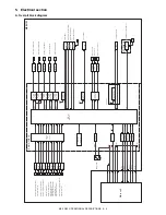
5. Electrical section
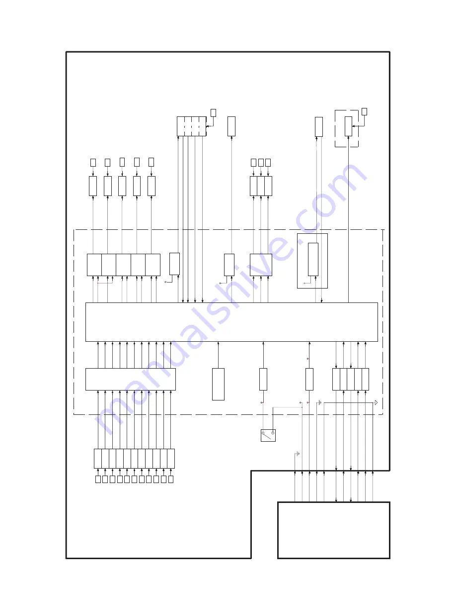
A. Overall block diagram
CPU
)
7
1
3
2
/
S
8
H
(
(ST
A
457C)
(2SB1240 x4)
+24V
+24V
+24V
P-GND
FG
W
S
S
F
F
A
PHPS-R
FPRD
F
A
PHPS-F
FSTPD
FDTLLS
FPLD
FDRPS
+5V
+5V
+5V
+5V
+5V
+5V
+5V
+5V
+5V
+5V
+5VR
FTPS
FPPD1
S-GND
MX-FN23
FDTPD
FPLS
+24VR
+24VR
+24V
Paper alignment motor F
Delivery roller lift motor
Paper delivery motor
Paper transport motor
Paper alignment motor R
H bridge circuit
T
ray lift motor
Paddle solenoid
Paper gate solenoid
Alignment roller lift solenoid
T
ransistor array
Fan motor drive circuit
Not installed
LED PWB UN
Illumination of the staple unit
Cooling fan motor
RxD-FIN
+3.3V
+5V
+24V
+24VR
TxD-FIN
DSR-FIN
/DTR-FIN
/RES-FIN
FINDET
Input buf
fer
Input buf
fer
Output buf
fer
Output buf
fer
Input buf
fer
3-terminal Reg
Input buf
fer
Safety switch
On-board
writing circuit
Main unit
FP
APD
FDRLPD
FPDPD
FPTPD
STLK
FCF-LD
FSL
FP
AM-F
FP
AM-R
FDRLM
FPDM
FPTM
FSM
FSHPS
FSED
FSLD
FTLM
FPGS
FPS
FA
R
L
S
FCF
FSL
+24V
+24V
+24VR
+24VR
+5V
+24VR
+5VR
(TD62003APG)
Paper rear edge detector
Paper alignment plate home
position sensor F
Staple tray paper detector
Paper level detector
Delivery tray lower limit sensor
Delivery tray position sensor
Paper pass detector
Delivery roller position sensor
Paper alignment plate home
position sensor R
Paper delivery tray paper detector
Paper level sensor
IF MAIN PWB UN
Sensor
in put
circuit
Chopping
circuit
(ST
A7101M)
Chopping
circuit
(ST
A7101M)
Chopping
circuit
(ST
A7101M)
Chopping
circuit
(ST
A7101M)
(ST
A7101M)
Chopping
circuit
H bridge circuit
Staple Motor
Staple home position sensor
Staple empty detector
Staple lead detector
Staple unit
(RQJ0602EGDQS)


