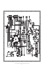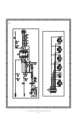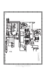
LL-T15S3
CONNECTION, ADJUSTMENT, OPERATION, AND FUNCTIONS
2 – 3
2. ADJUSTMENT
2-1. ADJUSTMENT METHOD
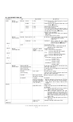
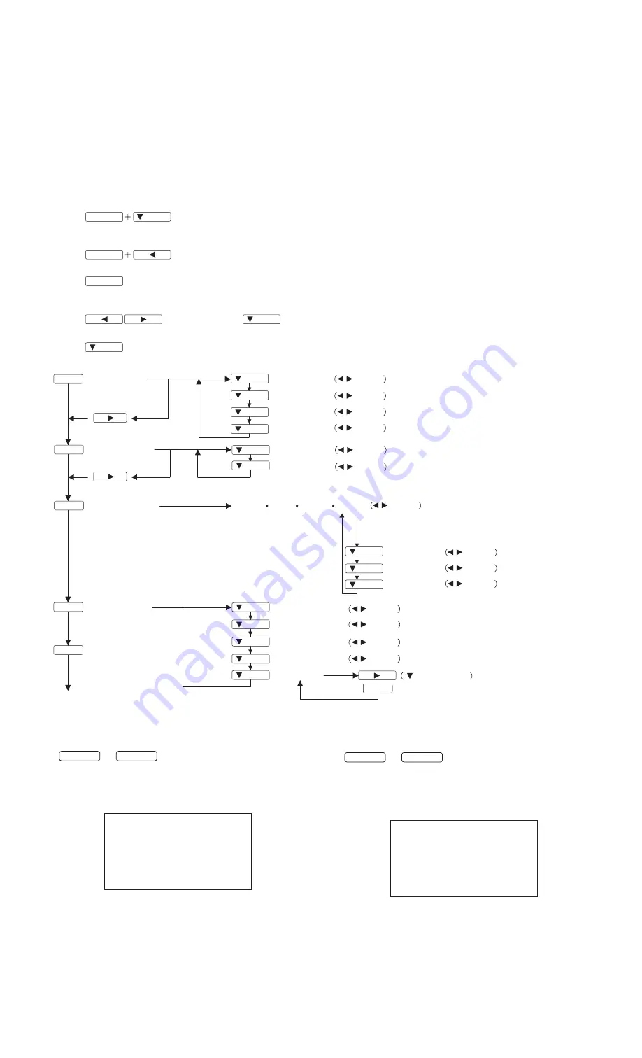
6) Version display (for service)
Power ON
Display the software version.
Press the above two buttons at same time, and while turn the power
on.
7) Aging (for service)
Power ON
Press the
d
button, Screen color is changed as following.
Green
3
Blue
3
Gray
3
White
3
Light Red
3
Light Green
3
Pink
3
Red
When the test is terminate, Power off
MENU
MENU
MENU
4) Adjusting the backlight and speaker volume
buttons (Press the
button and select "BRIGHT" or "VOLUME".)
5) Setting color mode
button (STD, sRGB, VIVID)
1) Resetting all adjustment values
Power ON
Power ON
Press the above two buttons at same time, and while turn the power on.
2) ADJUSTMENT menu reset
Press the two buttons at same time.
3) Adjustment lock function
While pressing the MENU button, turn the power on.
6) Screen adjustment
MENU
ADJUSTMENT
AUTO
CLOCK
PHASE
H-POS
V-POS
AUTO
MENU
GAIN CONTROL
BLACK LEVEL
CONTRAST
MENU
(COOL STD
WHITE BALANCE
WARM USER)
R-CONTRAST
CONTRAST
(R/G/B)
G-CONTRAST
B-CONTRAST
MENU
MODE SELECT
MENU
MENU
buttons
buttons
buttons
buttons
buttons
buttons
buttons
buttons
buttons
buttons
OSD H-POSITION
OSD V-POSITION
SCALING
buttons
buttons
buttons
COLORS
buttons
LANGUAGE
buttons
END
/MODE
/MODE
/MODE
/MODE
/MODE
/MODE
/MODE
/MODE
/MODE
/MODE
/MODE
/MODE
/MODE
/MODE
/MODE
/MODE
/MODE
/MODE
MENU
d
<VERSION & CHECK SUM>
VERSION
: 1.01 (200XXXXX)
CHECK SUM : OK XXXX
c
/MODE
e
AGING TEST
>
: SET
MENU :
END
Содержание LL-T15S3
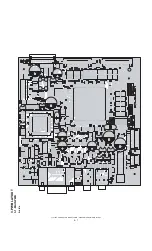
Страница 18: ...LL T15S3 CONNECTOR SIGNAL TABLE CIRCUIT DIAGRAM PWB LAYOUT 5 7 3 PWB LAYOUT 3 1 MAIN PWB A side ...
Страница 19: ...LL T15S3 CONNECTOR SIGNAL TABLE CIRCUIT DIAGRAM PWB LAYOUT 5 8 B side ...
Страница 20: ...LL T15S3 CONNECTOR SIGNAL TABLE CIRCUIT DIAGRAM PWB LAYOUT 5 9 3 2 POWER SUPPLY PWB ...


