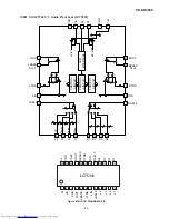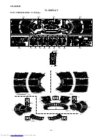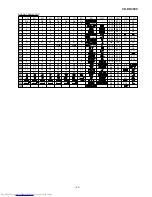
CD-DD4500
– 58 –
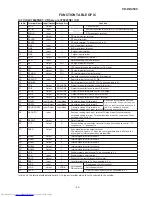
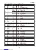
1
RST
Input
Hardware reset input terminal. (L: reset, R: normal operation)
2*
MIMD
Input
Microcomputer I/F mode select input terminal. (L: serial, H: I2C bus)
3
MICS
Input
Microcomputer I/F chip select input terminal.
4
MILP
Input
Microcomputer I/F latch pulse input.
5
MIDIO
Input/Output
Microcomputer I/F data input/output terminal.
6
MICK
Input
Microcomputer I/F clock input terminal.
7
MIACK
Output
Microcomputer I/F acknowledge output terminal.
8*
FI0
Input
Flag input terminal 0.
9*
FI1
Input
Flag input terminal 1.
10*
FI2
Input
Flag input terminal 2.
11*
FI3
Input
Flag input terminal 3.
12*
IRQ
Input
Interrupt input terminal.
13
VSS
—
Digital ground terminal.
14
LRCKA
Input
Audio I/F LR clock input terminal A.
15
BCKA
Input
Audio I/F bit clock input terminal A.
16
SDO0
Output
Audio I/F data output terminal 0.
17
SDO1
Output
Audio I/F data output terminal 1.
18
SDO2
Output
Audio I/F data output terminal 2.
19*
SDO3
Output
Audio I/F data output terminal 3.
20
LRCKB
Input
Audio I/F LR clock input terminal B.
21
BCKB
Input
Audio I/F bit clock input terminal B.
22
SDI0
Input
Audio I/F data input terminal 0.
23
SDI1
Input
Audio I/F data input terminal 1.
24
VDD
Input
Digital power supply terminal.
25
LRCKOA
Output
Audio I/F LR clock output terminal A.
26
BCKOA
Output
Audio I/F bit clock output terminal A.
27
TEST0
Input
Test input terminal 0. (L: test, H: normal operation)
28
TEST1
Input
Test input terminal 1. (L: test, H: normal operation)
29*
LRCKOB
Output
Audio I/F LR clock output terminal B.
30*
BCKOB
Output
Audio I/F bit clock output terminal B.
31*
TXO
Output
SPDIF output terminal.
32
TEST2
Input
Test input terminal 2. (L: test, H: normal operation)
33
TEST3
Input
Test input terminal 3. (L: test, H: normal operation)
34
RX
Input
SPDIF input terminal.
35
VSS
—
Digital ground terminal.
36
TSTSUB0
Input
Test sub input terminal 0. (L: test, H: normal operation)
37
FCONT
Output
VCO frequency control output terminal.
38
TSTSUB1
Input
Test sub input terminal 1. (L: test, H: normal operation)
39
TSTSUB2
Input
Test sub input terminal 2. (L: test, H: normal operation)
40
PDO
Output
Phase error signal output terminal.
41
VDDA
Input
Analog power supply terminal.
42*
PLON
Input
Clock select input terminal. (L: external clock, H: VCO clock)
43
AMPI
Input
Amplifier input terminal for LPF.
44
AMPO
Output
Amplifier output terminal for LPF.
45
CKI
Input
External clock input terminal.
46
VSSA
—
Analog ground terminal.
47
CKO
Output
DIR clock output terminal.
48
LOCK
Output
VCO lock detection output terminal.
49
VSS
—
Digital ground terminal.
50
WR
Output
External SRAM write signal output terminal.
51
OE
Output
External SRAM output enable signal output terminal.
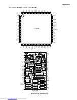
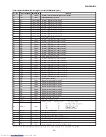
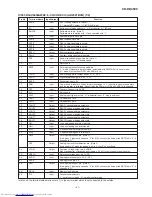
IC504 RH-iX0443AWZZ: Dolby Decoder (IX0443AW) (1/2)
Terminal Name
Pin No.
Input/Output
Function
In this unit, the terminal with asterisk mark (*) is (open) terminal which is not connected to the outside.
Содержание CD-DD4500
Страница 70: ...CD DD4500 70 MEMO ...
Страница 87: ...CD DD4500 16 MEMO ...


