Rev. 1
104 /
5.1.2.5 Test Print
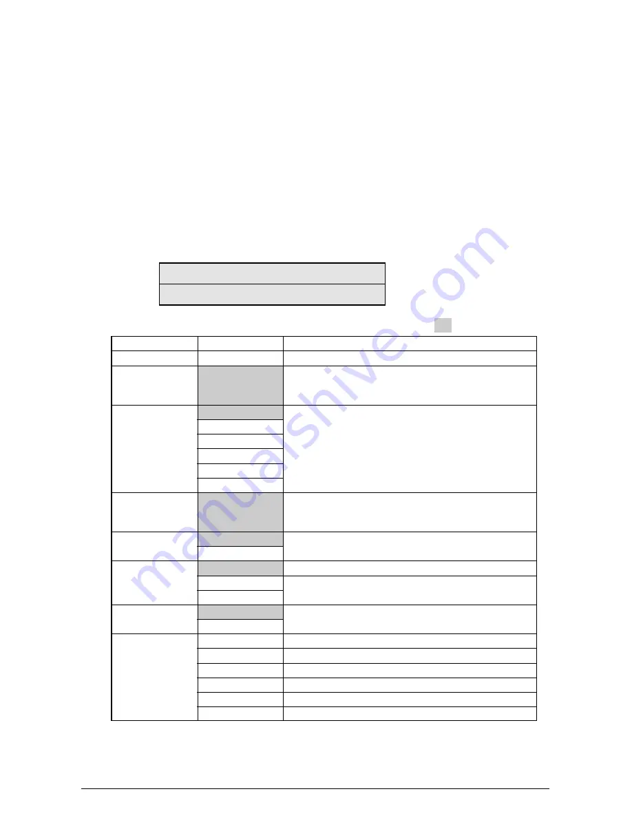
This self-diagnostic routine is used to print the test pattern in the PU. Other test patterns are stored
in the controller.
1.
Continue to press the [MENU+] and [MENU-] keys until “TEST PRINT” appears at the top
row of the display, and the system is in the self-diagnosis (Lever 1) mode. The [MENU+]
key = Increment Test Item / the [MENU-] key = Decrement Test Item.
2.
Press the [ENTER] key only for the setting item applied for test printing appears at the
bottom of the display. Press the [MENU+] and [MENU-] keys until the applicable item
appears. The [MENU+] key = Increment Item / the [MENU-] key = Decrement Item. (Go
to Item 5 to [Default Setting] if setting of each item is unnecessary.)
3.
Press the [ENTER] key for the setting item to appear on the top row of the display and
the setting value to appear at the bottom row of the display. Press the [MENU+] key for
the setting value to increment. Press the [MENU-] key for the setting value to decrement
(the final display setting value is applied). Accordingly repeat item 3.
TEST PATTERN
1
Display
PRINT EXECUTE
TEST PATTERN
CASSETTE
PAGE
COLOR
DUPLEX
JOB OFFSET
FINISHER
Setting value
0
TRAY1
TRAY2
TRAY3
TRAY4
TRAY5
MPF
0
ON
OFF
3 PAGES STACK
OFF
1 PAGES STACK
OFF
ON
OUTPUT BIN
PUNCH
OFFSET
STAPLE
STAPLE PAGE
INVERT
Function
Press [Enter] to start printing or [CANCEL] to stop printing (each page).
0: Blank page
1 to 7: See the “Test Print Pattern” table (pattern printing).
8 to 15: Blank page
Choose a paper feeder.
Set the number of test print pages. Press [ONLINE] to move
the cursor to the digit to be edited. Press [MENU_] to increase
the set value, and [MENU_] to decrease the set value.
Choose Color or Monochrome.
Prints on both sides of a stack of 3 sheets.
Turns off duplex printing.
Prints on both sides of one sheet.
Turns the job offset function on and off.
Choose an output bin.
Turns the punch mode on and off.
Turns the offset mode on and off.
Choose the staple location.
Set the number of sheets to be stapled (0 to 50).
Turns the invert mode on and off.
The settings shaded in are default settings.
*1 TRAY 2 to TRAY 5 and DUPLEX will be displayed only when their respective units are installed.
*2 If the finisher is not installed, “OUTPUT BIN” is displayed and only the output bin is selectable.
• Presets: FACE DOWN/FACE UP
Default: FACE DOWN
* These settings are valid in the test mode only (they will not be written to the EEPROM).
Содержание AR-C360P
Страница 2: ...Ver Date No Revision Page Changes In Charge Document Revision History ...
Страница 5: ...Rev 1 5 Do not go near an ejection area while the power is on and in printing You may get injured ...
Страница 9: ...Rev 1 9 ...
Страница 13: ...Rev 1 13 Finisher Unit AR C36TF 2 3 Hole Punch Unit AR C36HP No Image ...
Страница 16: ...Rev 1 16 ...
Страница 19: ...Rev 1 19 ...
Страница 40: ...Rev 1 40 ...
Страница 48: ...Rev 1 48 ...
Страница 51: ...Rev 1 51 4 2 Parts Layout Printer Unit 120V ...
Страница 52: ...Rev 1 52 Base Assy 1 2 A A ...
Страница 53: ...Rev 15 4 Base Assy 2 2 ...
Страница 54: ...Rev 1 55 Side R Assy ...
Страница 55: ...Rev 1 56 Side F Assy ...
Страница 56: ...Rev 1 56 Cover Assy OP Panel ...
Страница 57: ...Rev 1 57 FDR Unit Regist A A B B ...
Страница 58: ...Rev 1 58 FDR Unit MPT ...
Страница 59: ...Rev 1 59 Sensor Regist Assy ...
Страница 60: ...Rev 1 60 Eject Assy 2 ...
Страница 61: ...Rev 1 61 Plate Top Assy A A A A ...
Страница 62: ...Rev 1 62 Job Offset Assy ...
Страница 63: ...Rev 1 63 Basket Assy ...
Страница 64: ...Rev 1 64 Plate Shield Box Assy ...
Страница 65: ...Rev 1 65 Unit Duplex 1 2 8 ...
Страница 66: ...Rev 1 66 Unit Duplex 2 2 ...
Страница 87: ...Rev 1 87 Lever 1 4 3 20 Unit Duplex 1 Pull out Unit Duplex 1 while pressing the lever ...
Страница 89: ...2EV 89 ...
Страница 109: ...Rev 1 109 ...
Страница 161: ...Rev 1 161 Ground Charge roller Development roller Toner supply roller Development braid Figure 7 3 ...
Страница 169: ...Rev 1 169 8 2 Diagram of Part Layout of Various PCB ...
Страница 179: ...10 ERROR MESSAGE LIST Details undecided ...


