AM-900U
2 – 8
2. Diagnostic items description
2.1. Fax diagnosis
2.1.1 Soft switch mode
In this mode, the soft switches are set and the soft switch list is printed.
1. Operation
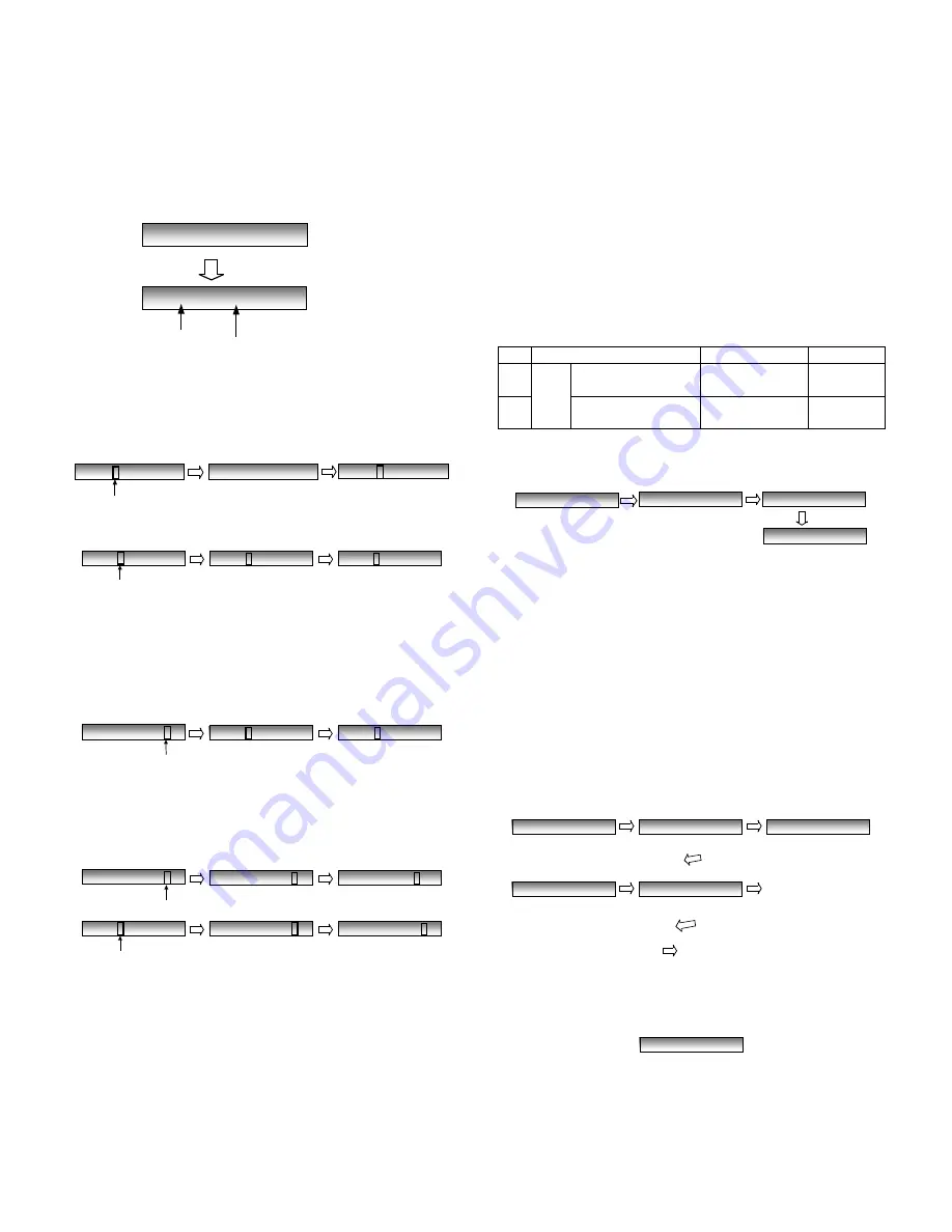
Soft switch mode screen
2. Switch number selection and data setting
1) Enter two digits of a soft switch number to set the switch num-
ber. Of a switch number of non-existing soft switch is entered,
key error buzzer sounds to reject the input.
2) Press [ENTER] key for setting of the next soft switch.
3) Data number selection
(a) Pressing [>] key moves the cursor to the right.
If the cursor is on data number 8, pressing [>] key shifts the cur-
sor to data number 1 of the next switch number. If the switch
number is the final, pressing [>] key will exit the soft switch
mode.
(b) Pressing [<] key moves the cursor to the left.
If the cursor is on data number 1, pressing [<] key shifts the cur-
sor to data number 1 of the former switch number. If the switch
number is 1, pressing [<] key do not move the cursor.
3. Data setting
Press the [MENU] key, and the data to the position of the cursor will
be reversed to 1 when it is 0, or to 0 when it is 1.
4. Outputting method of soft switch list
In the soft switch mode, press [QUALITY] key, and the soft switch
list will be printed. If the recording paper runs out or is clogged, the
key error buzzer will sound with the process not received.
5. Storage of data
In the following cases, the data if the soft switches set will be
stored.
• It is shifted to set the next soft switch by pressing [ENTER] key.
• It is shifted to set the next soft switch with the [>] key.
• It is shifted to the last soft switch with the [<] key.
• It is shifted to set another soft switch by inputting two digits as
the switch number.
• Output of the soft switch list starts.
6. Protocol monitor
If the SW No. 8 Data No. 5 is set to 1, the protocol monitor result is
printed after fax communication.
2.1.2 ROM & RAM check
To check the sum value of Firmware or RAM.
*1 WORK MEMORY (SDRAM 16M).
1. Display
2. Result printing
After checking, the results print starts.
2.1.3 Panel key test
This is used to check whether each key is normally operated or not.
When the test is started, a LED will blink (1000ms cycle) for the LED
test. During the test. After the test, the test result will be printed.
* When any numeric key is pressed during the panel test, the DTMF
signal correspond to the key number is sent to the line. If another key
is pressed the DTMF signal will stop. This function becomes valid by
changing the value of soft switch. (Default: Disable)
1) Flow
Press any key except [STOP] key. At this time, the name of each
key will be displayed every push of the key.
a) When all keys can be inputted, the following message will be dis-
played.
Then the screen will be all displayed in blank (Refer to (2)) and the
test result will be printed.
SOFTSWITCH MODE
[ENTER] Key
SW01 = 0 1 0 1 0 0 1 0
Switch No.
1 2 3 4 5 6 7 8: Data No.
SW01 = 0 1 0 1 0 0 1 0
cursor position
SW01 =
[ 1 ] key
SW16 = 0 1 0 1 0 0 1 0
[ 6 ] key
SW01 = 0 1 0 1 0 0 1 0
cursor position
SW02 = 0 1 0 0 1 1 0 0
SW03 = 0 1 0 0 1 1 0 0
[ENTER]Key
[ENTER]Key
SW01 = 0 1 0 1 0 0 1 0
cursor position
SW02 = 0 1 0 0 1 1 0 0
SW03 = 0 1 0 0 1 1 0 0
[>]Key
with the cursor on bit8
[>]Key
SW03 = 0 1 0 1 0 0 1 0
cursor position
SW03 = 0 1 0 0 1 1 0 0
SW03 = 0 1 0 0 1 1 0 0
[<]Key
[<]Key
SW03 = 0 1 0 0 1 1 0 0
cursor position
SW02 = 0 1 0 0 1 1 0 0
SW01 = 0 1 0 0 1 1 0 0
[<]Key
with the cursor on bit 1
[<]Key
No.
Device
Alarm Buzzer
Remarks
1
Main
ROM
(PROGRAM FLASH)
1 time <Short
sound>
2
D-RAM1(*1)
2 times <Short
sounds>
ROM & RAM CHECK
ROM =
RAM=
Start checking
by pressing [ENTER] key
ROM=OK,RAM=OK
PRINTING
To finish this mode, press [STOP] key
PANEL CHECK MODE
PRESS EACH KEY
1
[ENTER] key
[1]Key
1
[START]Key
START
Go to (a or b).
..... (other key)
ALL KEY OK !!
Содержание AM 900 - Digital Office Laser Copier
Страница 120: ...AM 900U 6 13 13 Control PWB parts layout Bottom side The CONTROL PWB of the model employs lead free solder F3 F5 F7 F4 ...
Страница 122: ...AM 900U 6 15 2 LIU PWB parts layout Top side The LIU PWB of the model employs lead free solder ...
Страница 123: ...AM 900U 6 16 3 LIU PWB parts layout Bottom side The LIU PWB of the model employs lead free solder ...


