8
8-1
8-2
25WF30
No.
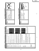
Adjustment point
Adjustment Condition / Procedure
W
aveform or others
1
2
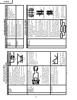
RF-AGC
T
AKE OVER
POINT
ADJUSTMENT
(I
2
C BUS
CONTROL)
1.
Receive the P
A
L
Colour bar signal.
Signal Strength: 54 ± 1 dbµV (75
Ω
open)
2.
Connect the oscilloscope to
TP201 (T
uner
’s
AGC
T
erminal) as shown in
Fig. 3
.
3.
Call "AG" mode in service mode.
Adjust the
"AG" bus data to obtain the
T
uner output pin
drop 0.1 ~ 1.0 V below maximum voltage.
4.
Change the antenna input signal to 63 ~
67 dBµV
, and make sure there is no noise.
5.
T
urn up the input signal to 90 ~ 95 dBµV to be
sure that there is no cross modulation beat.
Note:
For the 50
Ω
signal strength
gauge, when not using 50/75
impedance adapter
, signal
strength is 52 ± 1 dBµV (75
Ω
open), instead of 54 ± 1 dBµV
(75
Ω
open).
Precaution:
The loss of using impedance
adapter
.
T
uner IFT
(PRESET)
TU200
1.
Get the tuner ready to receive the CH. E-10
signal, but with no signal input.
Adjust the PLL data.
2.
Connect the sweep generator
’s
output cable
to the tuner antenna. (RF SWEEP)
3.
Adjust the sweep generator
’s
to 80dBµV
.
4
.
Connect the response lead (use LOW IMPED-
ANCE probe with wave detector ; see
Fig.1
)
to the tuner
’s
IF output terminal. (This terminal
must have the probe alone connected).
5.
Set the RF
AGC to 0 - 6 V with no saturation
with the waveform.
6.
Adjust the tuner IF coil to obtain the waveform
as shown in
Fig. 2
.
Note:
Be sure to keep the tuner cover in position
during this adjustment.
SER
VICE ADJUSTMENT
PIF ADJUSTMENT
CHECKING
3
PIF VCO COIL
ADJUSTMENT
1.
Do not receive any signal.
2
.
Connect the digital voltmeter to
TP803 (pin (54)
of IC800) in the main unit.
3.
Call the "PIF VCO" Mode at the service mode.
4.
V
erify that it is turned counterclockwise to 0V
and adjust
T800 to make DC voltage of
TP803
become 2.5 ± 0.1 V in the range.
DC voltage at
TP803
Adjust
T800 to B point, between B'
and B".
*
T
urn the coil counterclockwise for
the up direction and clockwise for
the down direction.
Fig.
1
Fig.
2
E-9 CH
P C
-1.5+/-0.8dB
10k
100k
1n60
75ohm
IF OUT
1000p
Oscilloscope
Fig.
3
Oscilloscope
BIAS Bo
x
TV SET
Bias Bo
x :
about 4.5V
TP201
0.1V
+
–
+
–
5V
2.5V
Down
BB
"
C
U
P
B’
A
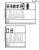
No.
Adjustment point
Adjustment Condition / Procedure
W
aveform or others
Note:The setting below is automati-
cally set when the SUB-VOL is
selected in the service mode.
*
SURROUND OFF
*
A
V MODE (ST
ANDARD)
*
S-NORMAL state
*
S-VOL Max
*
Bass + OFF
SOUND ADJUSTMENT
1
SUB VOL
(BUS
ADJUST
-
MENT)
1.
Receive P
A
L
Colour Bar signal.
Signal content: 400 Hz 100% Mod.
2.
Connect the probel of the meter (*) to (SI) con-
nector
.
3.
Select the SUB-VOL in the service mode.
4.
Adjust the SUB-VOL data to make the meter
indicate 5.2 V
rms (at L-CH)
Adjustment value: 5.0
±
0.3
V
rms
2
NOISE MUTE
CHECKING
1.
Receive the P
A
L
Colour Bar signal.
2
.
T
urn up the volume control to maximum, make
sure the sound is heard from the speakers.
Then put the unit in no signal state.
3.
Check the sound mute is ef
fective.
4.
Finally turn sound level of CTV to minimum.
No.
Adjustment point
Adjustment Condition / Procedure
W
aveform or others
1
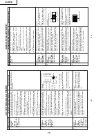
PURITY
ADJUSTMENT
1.
Select the green monocolour screen with re-
mote controller
, and set the beam current of
1,400µA with the contrast control.
2.
Degauss the CR
T
enough with the degausing
coil. For the adjustable magnetic field.
V
ertical Bv:
0.1G
Horizontal Bh:
0.1G
3.
Maintain the purity magnet at the zero mag-
netic field and keep the static convergence
roughly adjusted.
W
ith P-MG, adjust it to the center - rank
A.
4.
Observe the points a, b, as shown in
Fig.4-1
through the microscope. Move DY fore and aft
to set the landing at the point (rank
A).
5.
If the a/b balance is poor
, compensate it to the
center "Rank
AB).
6.
Align it to zero, keeping the raster rotation in
the east direction.
7.
T
ighten the defrection coil fastening screw
.
T
ightening torqu: 180N ± 20N (1
1kgf ± 2kgf)
8
.
Checking the CR
T
corner area, bond the mag-
netic sheet to set the landing at Rank
A
for
compensation.
Note:This adjustment must be done after
warming up the unit for 30 minutes or longer
with a beam current over 1400 ± 50 µA.
Note:Select the service mode, and press the
monocolour key of R/C for process,and the
monocolour screen (green) will be selected.
Every push of the monocolor key changes the
screen as follows.
PURITY
ADJUSTMENT
*
Press R/C RGB key for 1 sec-
ond in NORMAL MODE, the col-
our will change to RGB mono
colour mode.
Fig.
4-1
Fig.
4-2 Rank A (On the right of CR
T)
Fig.
4-3 Rank A (On the left of CR
T)
a
A
A=B
B
A
A=B
B
b
90 mm
90 mm
GREEN
ONL
Y
BLUE
ONL
Y
Single-colour
screen cleared
RED
ONL
Y
*
Adjustment for uniformity is
changed to another content.
Please refer to the following
page.
Содержание 25WF30
Страница 18: ...6 5 4 3 2 1 A B C D E F G H 18 25WF30 CHASSIS LAYOUT ...
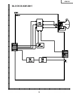
Страница 19: ...6 5 4 3 2 1 A B C D E F G H 19 25WF30 BLOCK DIAGRAM 1 ...
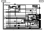
Страница 20: ...21 25WF30 20 25WF30 8 7 10 9 6 5 4 3 2 1 A B C D E F G H 17 16 19 18 15 14 13 12 11 BLOCK DIAGRAM 2 ...
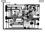
Страница 21: ...23 25WF30 22 25WF30 8 7 10 9 6 5 4 3 2 1 A B C D E F G H 17 16 19 18 15 14 13 12 11 BLOCK DIAGRAM 3 ...
Страница 22: ...25 25WF30 24 25WF30 8 7 10 9 6 5 4 3 2 1 A B C D E F G H 17 16 19 18 15 14 13 12 11 BLOCK DIAGRAM 4 ...
Страница 23: ...6 5 4 3 2 1 A B C D E F G H 26 25WF30 BLOCK DIAGRAM 5 ...
Страница 26: ...6 5 4 3 2 1 A B C D E F G H 29 25WF30 SCHEMATIC DIAGRAM CRT Unit ...
Страница 30: ...6 5 4 3 2 1 A B C D E F G H 36 25WF30 SCHEMATIC DIAGRAM OPERATION Unit ...
Страница 31: ...6 5 4 3 2 1 A B C D E F G H 37 25WF30 PWB C CRT Unit Wiring Side PRINTED WIRING BOARD ASSEMBLIES ...
Страница 35: ...6 5 4 3 2 1 A B C D E F G H 44 25WF30 PWB D OPERATION Unit Wiring Side ...


