13
Configuring the device
The G-1 Beam Series can be set up by using the display panel at the yoke of the fixture.
Please note: In POI versions there is no display mounted in the fixture. The adjustments are made through RDM.
See page 24 to know more.
Before turning on the G-1 Beam, make sure the power cable is properly
connected, or the batteries are charged (when the fixture is ruining on batteries).
After powering the fixture, the display shows the currently selected operating
mode, the DMX start address and other information. Navigate through the
menus using the arrows and select items using the ENTER button.
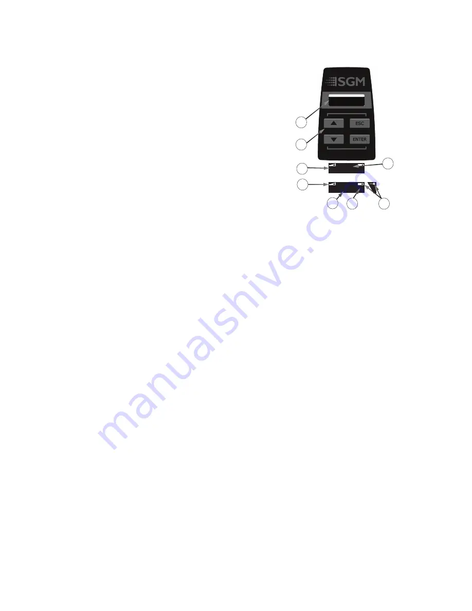
OLED Display (A)
The OLED display is the human interface of the fixture as it displays the current
status and menu of the fixture. The display panel can be used to configure
individual fixture settings, check the fixture’s wireless status, confirm the
firmware version, and read error messages. The complete list of the menu and
all commands available are listed in “Control Menu” on page 21.
Using the keyboard (B)
•
Press the ‘ENTER’ button to access the menu or make a selection.
•
Press the arrows to scroll up and down in the menus.
•
Press the ‘ESC’ button to take a step back in the menu or exit the
menu.
•
Press any button to disable pan/tilt - it generates time out for 10 sec.,
after which it will return to the correct position.
•
Press UP + DOWN arrows simultaneously = flip the display upside-down.
•
To turn off the G-1 Beam, press and hold the ‘ESC’ button until the fixture turns off or go to MENU → POWER OFF.
•
To turn on the G-1 Beam when running on batteries, press and hold any button for approx. 1 sec.
•
To turn on the G-1 Beam when running of cabled power, press any button and the fixture will power on instantly.
•
Press any button to disable pan/tilt (it generates time out for 10 sec., after which it will return to the correct position).
Active input type (C)
The active input is displayed for quick and simple verification of the input status.
•
When ‘DMX’ is displayed: The fixture responds to data received through cabled DMX.
•
When ‘CRMX’ is displayed: The fixture responds to data received through wireless DMX.
Wireless signal strength (D
)
Displays the signal strength of the wireless CRMX connection. The wireless signal strength symbol will be flashing if the paired
transmitter is out of range. If no transmitter is paired the symbol will be off.
Error indicator (E)
If any errors are detected, the message ‘ERR’ will be flashing in the display for easy detection.
To read the error message go to: MENU → INFO → ERRORS.
DMX address (F)
Displays the current DMX address. The DMX address can be changed directly from this view. The next available DMX address is
displayed to the right. The DMX address will be flashing if no data input.
Next fixture address (G)
Showing the next available DMX address depending on the fixture’s DMX footprint.
Current power source / battery level (H)
Displays the current power source, indicated by a power cable symbol (running on AC power) or a battery symbol. When running on
battery, it is displays the current battery level.
113
DMX
(131)
INFO
SETTINGS
TEST
RESET
Lorem ipsum dolor sit amet,
consectetuer adipiscing elit,
sed diam nonummy nibh
DMX
ERR
(113)
(113)
DMX
DMX
101
10
(113)
1
101
(113)
DMX
A: OLED Display E: Error indicator
B:
Keyboard
F:
Current
DMX
address
C: Active input type G: Next available DMX address
D: Wireless signal strenght H: Battery level / running AC power
B
D
A
H
E
C
G
F
Figure 13: Control panel
Содержание G-1 BEAM
Страница 1: ...USER MANUAL MOVING HEADS SERIES G 1 BEAM G 1 BEAM POI ...
Страница 30: ...30 User Notes ...
Страница 31: ...31 User Notes ...
Страница 32: ...32 SGM Light A S Sommervej 23 8210 Aarhus V Denmark Tel 45 70 20 74 00 info sgmlight com www sgmlight com ...


