


54
Manual – DFD11B DeviceNet Fieldbus Interface
6
Process data exchange
DeviceNet Characteristics
6
DeviceNet Characteristics
6.1
Process data exchange
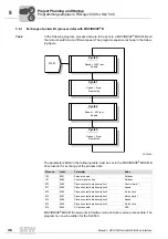
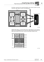
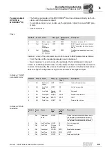
Polled I/O
The polled I/O messages correspond to the process data telegrams of the SEW fieldbus
profile. Up to 10 process data words (for operation with MOVIDRIVE
®
B) or up to 24 pro-
cess data words (for Gateway operation) can be exchanged between the control and
DFD11B. The process data length is set via DIP switches S2-PD0 ... S2-PD4.
Timeout
response with
polled I/O
The timeout is triggered by the DFD11B option. The timeout interval must be set by the
master after the connection has been established. The DeviceNet specification refers to
an 'expected packet rate' rather than a timeout interval in this case. The expected packet
rate is calculated on the basis of the timeout interval using the following formula:
t
Timeout_inverter
= t
Timeout interval_Polled_I/O
= 4 x t
Expected_Packet_Rate_Polled_I/O
The expected packet rate can be set using the connection object class 5, instance 2,
attribute 9. The range of values runs from 0 ms to 65535 ms in 5 ms steps.
The expected packet rate for the polled I/O connection is converted into the timeout in-
terval and displayed in the device and the timeout interval in parameter P819.
This timeout interval is retained in the device whenever the polled I/O connection is
dropped, and the device switches to timeout status after the timeout interval has
elapsed.
The timeout interval must not be altered in the inverter using MOVITOOLS
®
or the
DBG60B keypad, because it can only be activated via the bus.
If a timeout occurs for the polled I/O messages, this connection type enters timeout sta-
tus. Incoming polled I/O messages are no longer accepted.
The timeout causes the timeout reaction set in the inverter to be carried out.
The timeout can be reset with DeviceNet by means of the reset service of the connection
object (class 0x05, instance 0x02, undetermined attribute), by disconnecting the con-
nection, by means of the reset service of the identity object (class 0x01, instance 0x01,
undetermined attribute) or with the reset bit in the control word.
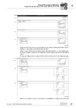
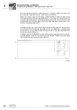
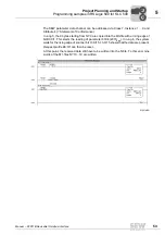
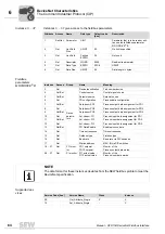
Bit-strobe I/O
Bit-strobe I/O messages are not contained in the SEW fieldbus profile. The messages
represent a DeviceNet-specific process data exchange. The master sends a broadcast
message that is 8 bytes (= 64 bits) long. One bit in this message is assigned to each
station in accordance with its address. The value of this bit may be 0 or 1, triggering two
different responses in the recipient.
NOTE
The set process data length influences the process data lengths of both the polled I/O
and the bit-strobe I/O messages.
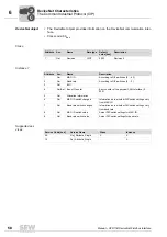
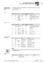
The process data length of the bit-strobe I/O messages can include up to four process
data words. If the value for the process data length set via DIP switches is less than
four, it will be accepted. If the value set via DIP switches is greater than four, the pro-
cess data length will be automatically limited to four.
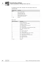
Bit
value
Meaning
BIO LED
0
Sends back process input data only
Green light
1
Trigger fieldbus timeout reaction and send back process input data
Green light
0
0
I
Содержание DFD11B
Страница 2: ...SEW EURODRIVE Driving the world...


