


3
Assembly / Installation Instructions
Installation of MOVI-PLC® basic DHP11B.. controller
18
Manual – MOVI-PLC
®
basic DHP11B.. controller
Cable length
• The permitted total cable length depends on the baud rate setting of the system bus:
– 125 kBaud
Æ
320 m
– 250 kbaud
Æ
160 m
–
500 kBaud
Æ
80 m
– 1000 kbaud
Æ
40 m
Terminating
resistor
• Switch on the system bus terminating resistor at the start and end of the CAN 2
system bus connection (MOVIDRIVE DIP
®
B, switch S12 = ON; MOVITRAC
®
B, DIP
switch S1 = ON). For all other devices, turn off the terminating resistor (MOVI-
DRIVE
®
B, DIP switch S12 = OFF; MOVITRAC
®
B, DIP switch S1 = OFF). If the
MOVI-PLC
®
basic
DHP11B.. controller is, for example, located at the end of the
CAN 2 system bus, you have to connect a terminating resistor of 120
Ê
between pins
X32:2 and X32:3 (for CAN 1: terminating resistor between pin X33:2 and pin X33:3).
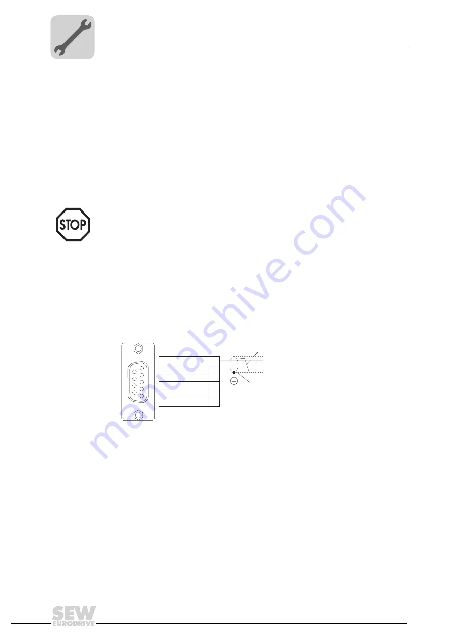
3.4.4
Connecting PROFIBUS (connector X30)
Connection to the PROFIBUS system using a 9-pin sub D connector in compliance with
IEC 61158. The T-bus connection must be made using a connector with the corre-
sponding configuration. The following figure shows the PROFIBUS connector that is
connected to X30 of the MOVI-PLC
®
basic
DHP11B.. controller.
Connecting
MOVIDRIVE
®
/
PROFIBUS
As a rule, the MOVI-PLC
®
basic
DHP11B.. controller is connected to the PROFIBUS
system using a shielded twisted-pair cable. Observe the maximum supported trans-
mission rate when selecting the bus connector.
The twisted-pair cable is connected to the PROFIBUS connector at pin 3 (RxD/TxD-P)
and pin 8 (RxD/TxD-N). Communication is carried out via these two pins. The RS485
signals RxD/TxD-P and RxD/TxD-N must all be connected to the same contacts in all
PROFIBUS stations. Otherwise, the bus components cannot communicate via the bus
medium.
• There
should
not
be any potential displacement between the units connected via the
CAN 2 system bus.
• There
must
not be any potential displacement between the units connected via the
CAN 1 system bus.
• Take suitable measures to avoid potential displacement, such as connecting the unit
ground connectors using a separate cable.
20059AXX
Fig. 5: Assignment of 9-pin sub D plug to IEC 61158
[1] 9-pin sub-D connector
[2] Signal line, twisted
[3] Conductive, wide area connection is necessary between the connector housing
and the shield
RxD/TxD-P
3
1
5
9
6
8
4
5
6
9
VP (P5V/100mA)
DGND (M5V)
DGND (M5V)
CNTR-P
RxD/TxD-N
[3]
[1]
[2]
Содержание MOVI-PLC basic DHP11B-T0
Страница 2: ...SEW EURODRIVE Driving the world ...
Страница 95: ...SEW EURODRIVE Driving the world ...


