5
Electrical installation
Connecting the motor and encoder system via KK terminal box
Operating Instructions – CM3C63 – 100
67
5.8.7
Power connection on terminal box
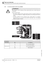
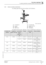
The following figure shows the power connection in the terminal box.
[1]
[2]
[6]
[7]
[8]
[3]
[5]
[4]
18014401410364299
[1]
Terminal stud
[5]
Terminal board
[2]
Top nut
[6]
Customer's cable
[3]
Washer
[7]
Bottom nut
[4]
Motor cable
[8]
Lock washer
For designing the terminal box, positions 4, 6 and 7 are regarded as current-carrying.
Terminal stud
diameter
Tightening
torque of hex nut
Connection
by cus-
tomer
Design
Connection
type
Scope of delivery
Cross sec-
tion
M4
1.6 Nm
≤ 6 mm
2
Version 1b
Ring cable lug Preassembled terminal
links
≤ 6 mm
2
Design 2
Ring cable lug
Small connection ac-
cessories enclosed in
bag
M5
2.0 Nm
≤ 10 mm
2
Design 2
Ring cable lug
Small connection ac-
cessories enclosed in
bag
M6
3.0 Nm
≤ 16 mm
2
Design 3
Ring cable lug
Small connection ac-
cessories enclosed in
bag
M8
6.0 Nm
≤ 25 mm
2
Design 3
Ring cable lug Premounted connection
pieces
M10
10.0 Nm
≤ 50 mm
2
Design 3
Ring cable lug Premounted connection
pieces
26870460/EN – 05/2021
Содержание CM3C63-100
Страница 2: ...SEW EURODRIVE Driving the world ...
Страница 117: ......
Страница 118: ......
Страница 119: ......


