background image

8

Installation and Service Manual

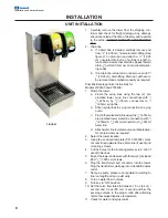
FIGURE 1

INSTALLATION

UNIT INSTALLATION

1.

Carefully remove the tower from the shipping con-
tainer and check for freight damage. Any damage
should be noted at the time of delivery and reported
to the carrier. DO NOT DISCARD ACCESSORIES
BAG.

2.

Drain line:
a.

If a drain line is desired, carefully remove end
from 

3

/

4

" (1.905 cm) horizontal drain fitting (See

figure 2) on drain pan and attach a 

3

/

4

" (1.905

cm) insulated drain line of sufficient length to
reach drain. Assure that drain line slopes toward
drain 

1

/

8

" per foot (0.5cm per m) or per local plumb-

ing codes.

b.

If no drain line is desired, do not remove end of 

3

/

4

" (1.905 cm) drain fitting. Drain pan will have to

be removed and emptied manually as required.

Post Mix Beverage Valve Instructions for
Models 2703405 and 2703406:
1.

Plumb the tower.
a.

Plumb the syrup lines using the two (2)  pre
plumbed tower syrup line connections with 

1

/

4

"(.635cm) by 

3

/

8

“(.95cm) connectors to 

3

/

8

“(.95cm) syrup line.

b.

Attach syrup lines to syrup connection on syrup
pump.

c.

Plumb the water/soda line using the 

1

/

4

"(.635cm)

pre plumbed tower water line connection with 

1

/

4

"(.635cm) X 

3

/

8

“(.95cm) connector to a 

3

/

8

“(.95cm)

water line.

d.

Attach water line to water source, carbonated wa-
ter or plain water as required.

2.

Select the tower location.

3.

Using the enclosed template (P.N. 5012434), mark
cut outs for syrup/water lines, drain line (if used) and
mounting screws.

4.

Cut the holes for the incoming water, syrup, and (if
used) drain lines.

5.

Mount the tower and secure with the two (2) enclosed
#8 X 

3

/

4

" (1.905 cm) screws.

6.

Plug the transformer butt connector into the tower.
Plug the transformer wall plug into a standard duplex
outlet.

7.

Set syrup pump pressure on regulator according to
line run length and syrup viscosity.

8.

Turn on water flow to valves.

9.

Turn key to “ON” position.

10. Set the valve flow rates to between 1.5 oz (44 cc) /

second and 3.0 oz (88 cm) / second and brix the
beverage valves to the proper ratio after attaining
normal beverage dispense temperature.

11. Check for water and syrup leaks.

Содержание 5030763

Страница 1: ...367 4233 Fax 812 246 9922 www manitowocbeverage com In accordance with our policy of continuous product development and improvement this information is subject to change at any time without notice Sep...

Страница 2: ......

Страница 3: ...___________________________________________________ Serial Number _______________________________________________________________________ Installation Date ____________________________________________...

Страница 4: ...5 ADDITIONAL WARNINGS 5 GROUNDING IN STRUCTIONS 6 INSTALLATION 7 UNIT INSPECTION 7 PRE INSTALLATION CHECK LIST 7 UNIT INSTALLATION 8 UNIT INSTALLATION 9 OPERATION 9 STARTING YOUR FLAVOR SHOT BEVERAGE...

Страница 5: ...concentration of CO2 gas causes tremors which are followed rapidly by loss of consciousness and suffocation If a CO2 gas leak is suspected particularly in a small area immediately ventilate the area...

Страница 6: ...ed by a qualified electrician WARNING When using electric appliances basic precautions should always be followed in cluding the following a Read all the instructions before using the appliance b To re...

Страница 7: ...onnectors for Figal tank Gas connectors for Figal tank Beverage dispenser Beverage tubing CO2 tank Figal beverage tanks Stepless Oetiker clamps Chain for CO2 tank Double Check Do you have enough space...

Страница 8: ...cm by 3 8 95cm connectors to 3 8 95cm syrup line b Attach syrup lines to syrup connection on syrup pump c Plumb the water soda line using the 1 4 635cm pre plumbed tower water line connection with 1 4...

Страница 9: ...ealth codes BEVERAGE VALVES Post mix beverage valves are designed to precisely meter the flow of both water and syrup to obtain the proper mixing ratio The syrup and soda water components of the post...

Страница 10: ...ng your Servend dispenser in top condition Following the guidelines below will assist you in continued trouble free operation of your unit Contact MBE at 1 800 367 4233 for more information about our...

Страница 11: ...rfaces of the unit with warm water and a clean cloth Wipe again with a clean dry cloth 5 Turn nozzle clockwise to the stop Pull the nozzle downward to remove Grasp diffuser and pull down ward to remov...

Страница 12: ...solution through the sys tem and out the beverage valve for 2 minutes Then allow the remaining detergent stay in the system for 5 minutes 6 Remove the valve nozzles and diffusers as de scribed in the...

Страница 13: ......

Страница 14: ......

Страница 15: ......

Страница 16: ......

Страница 17: ......

Страница 18: ...location 7 M MBE 3 Model Number 3 modifications 5 O Operation 5 P Power outlet 7 Q Qualified Service Personnel 5 R Relocation 5 return procedures 3 S SAFETY 5 6 sanitizing 4 Serial Number 3 service as...

Страница 19: ......

Страница 20: ...47172 1868 Tel 812 246 7000 800 367 4233 Fax 812 246 9922 www manitowocbeverage com In accordance with our policy of continuous product development and improvement this information is subject to chan...

Отзывы: