4
SERIAL CABLES NVMe JBOF User’s Manual
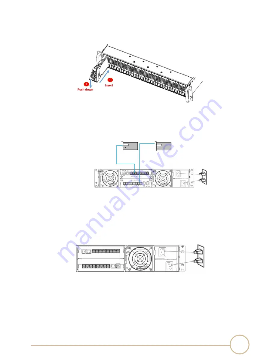
5. Insert the drive module into the PCI-ENC8G-024U enclosure correctly until its lever appears to
shut, and then press the lever to close until it clicks to ensure that the drive module is within
the enclosure.
6. Repeat steps 2 to 5 for further drives.
7. Connect PCI-ENC8G-024U enclosure to the host interface: An external PCIe host adapter card
through an SFF-8644 mini-SAS HD data cable. The connection between the PCI-ENC8G-024U
enclosure and the external PCIe host adapter ports is shown as follows:
8. Connecting PCI-ENC8G-024U enclosure’s USB Port (optional)
‧
PCI-ENC8G-024U enclosure’s system functions can be managed via a COM port running a
VT-100 terminal emulation program, or a VT-100 compatible terminal.
9. The PCI-ENC8G-024U enclosure provides a redundant power supply unit. Connect one end of
the two power cords to the two receptacles on rear of PCI-ENC8G-024U enclosure, and then
connect the other end of the two power cords to the power outlets.
11. After the two power cords are connected, you can power on the PCI-ENC8G-024U enclosure
and the computer.
2.3
Components location definition
Содержание PCI-ENC8G-024U
Страница 1: ...SERIAL CABLES NVMe JBOF User s Manual PCI ENC8G 024U NVMe 2U24Bay JBOF User s Manual Revision 1 2...
Страница 20: ...17 SERIAL CABLES NVMe JBOF User s Manual...
Страница 43: ...40 SERIAL CABLES NVMe JBOF User s Manual Load firmware file Click Load Hex File button to select firmware file...
Страница 45: ...42 SERIAL CABLES NVMe JBOF User s Manual Disconnect serial port and power cycle the system...


