


INSTALLATION AND OPERATION INSTRUCTIONS — PERSONAL ALARM SYSTEM
22
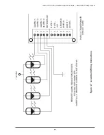
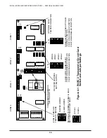
3.3.8
Be careful with connections to the remote zone alarm outputs, TB2, ALM1
through ALM4. These outputs have very limited current capability and are meant to
power a small local lamp, audible or LAP only. Each output is an open collector-type
drive with 40 milliampere current capability. A lamp or audible device must be rated
for 12 VDC and current not greater than 40 milliamperes. Connect the remote device
between the power supply and the correct ALM point. Connect REF (pin 5) to the
return side of the power supply. See Figure 3-6 for typical connections.
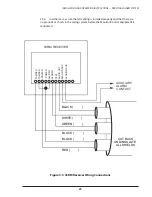
3.3.9
If a LAP unit is to be connected to the PARC-3 for local annunciation of alarms,
install jumpers JP 17 through JP 20 to configure the PARC-3 alarm outputs as LAP
outputs. Connect the LAP to the PARC-3 with the same 3 pair cable used to connect
the 03RM’s to the PARC-3. See figure 3-7 for connections.
NOTE: ALM1 through ALM4 are non latching signal outputs that follow the 03RM
alarm LED and will remain on as long as a nearby PAT is transmitting.
3.3.10 Configure the audio jumpers for each zone to provide the desired audio
features including (1) audio on alarm; (2) on alarm and on command, (3) on command
only; and (4) disabled.
3.3.11 Following completion of all connections to the PARC-3, take a moment to
verify that all connections are secure and proper. Before installing cover, verify that
the PARC-3 transponder addresses have been correctly set and that all jumpers are
installed in the correct position. See Initial Setup section. You may wish to leave the
covers off each PARC-3 until initial testing is complete.
NOTE: Each PARC-3 can be tested using the self-test function of the MX-2000.
Refer to the Initial Testing Section of this manual and the self-test portion of the
MX-2000 installation and operation instructions.
3.4
Central Control Installation
3.4.1
The installation of equipment at central control varies somewhat depending
on whether the MX-2000 or the DCU Communication Encoder/Decoder System is
used.
3.4.2
If the MX-2000 is being installed, please refer to the MX-2000 Installation and
Operation Instruction Manual.
3.4.3
If the DCU Communication Encoder/Decoder System is being installed please
refer to the DCU Installation and Operation Manual.


