MX-7000 Installation and operation manual
P a g e
| 28
Transformer setup (120 V/220 VAC input)
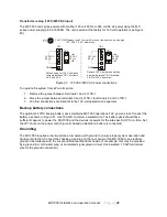
The MX-7000 unit can be powered from either 120 volt 60 Hz or 220 volt 50 Hz power using the MX
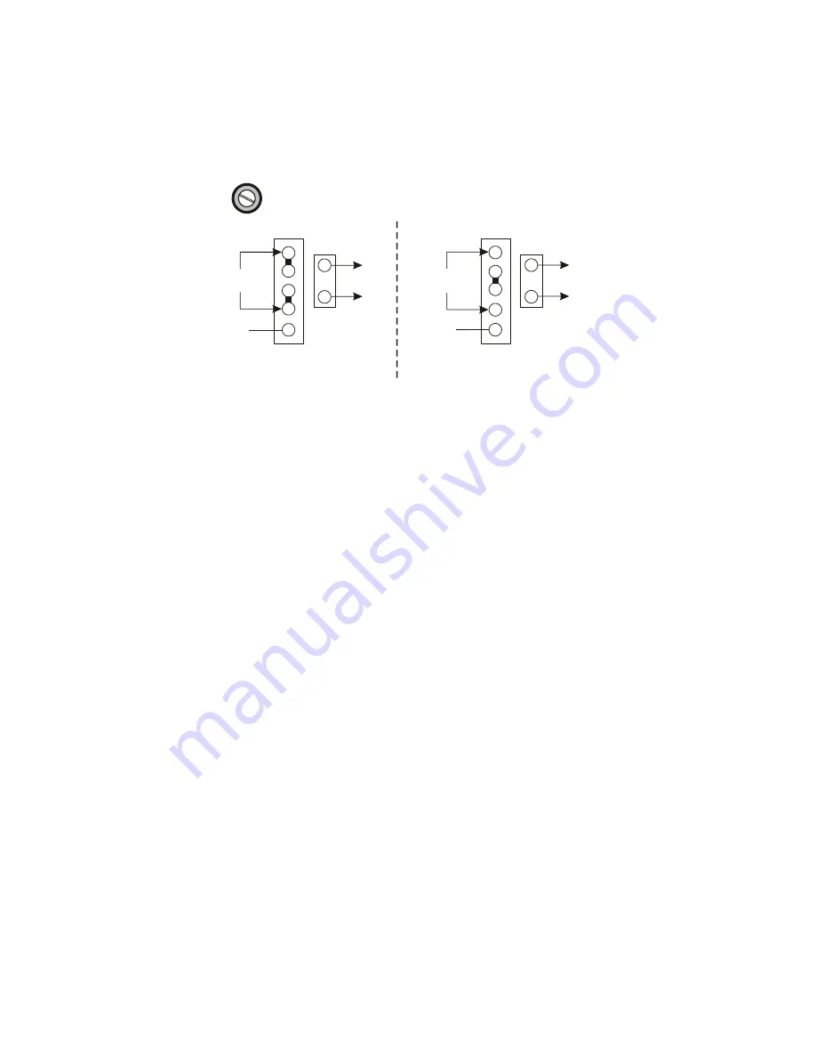
series power supply (p/n 02-190008). The unit is wired at the factory for 120 volt operation (see Figure
20).
Figure 20 120 VAC/220 VAC power connections
To operate the system from 220-volt service:
1. Remove the jumper between terminals 1 and 2 of TB-1.
2. Move the jumper between terminals 3 and 4 of TB-1 to terminals 2 and 3 of TB-1.
3. All other connections are identical to the 120-volt operation arrangement.
Backup battery connections
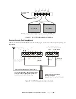
The optional 24 VDC backup battery pack maintains MX-7000 operations if AC power is lost. Connect the
battery as shown in Figure 21. Use 18 AWG minimum insulated wire. The battery pack should have
sufficient capacity to power the MX-7000 and the devices it powers for the site-specific UPS run-time. Set
the JP1 shunt on the power card (Figure 5) based on whether a battery is connected.
Grounding
The MX-7000 requires a low impedance, low noise earth ground to ensure proper system operation and
transient protection. Connect the chassis ground lug on the rear panel of the MX-7000 to an electrical
ground in accordance with the Local and National Electrical Codes. (For example, this may be provided
by a ground rod, cold water pipe, or an isolated signal ground circuit. Use insulated, 10 AWG minimum
wire for the ground connection.)
TB-1
TB-2
220 VAC
50 Hz
24 VAC
50 Hz
Remove 120 V jumpers and place
a jumper between TB-1 terminals
2 & 3 for 220 V operation.
1
2
3
4
1
2
TB-1
TB-2
120 VAC
60 Hz
24 VAC
60 Hz
1
2
3
4
1
2
Default setup for 120 V operation.
Jumpers between TB-1 terminals
1 & 2 and 3 & 4.
5
5
GND
F1
CAUTION: Replace fuse F1 only with a fuse of the same value and type
(3 A 250 V 3 AG slow blow).
GND

