MX-7000 Installation and operation manual
P a g e
| 44
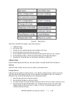
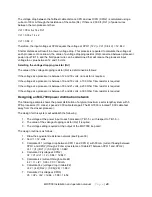
8. Calculate lc3 (current through cable #3)
lc3 = l1 + l2 + l3 = 0.03 + 0.03 + 0.03 = 90 mA
9. Calculate Vc3 (voltage drop in cable #3)
Vc3 = (lc3) (Rc3) = (0.09) (28) = 2.52V
10. Calculate V4 (voltage at XPO4)
V4 = V3 + Vc3 = 14.52 + 2.52 = 17.04V
11. Calculate lc4 (current through cable #4)
lc4 = I1 + l2 + l3 + l4 = (4) (0.030) = 120 mA
12. Calculate Vc4 (voltage drop in cable #4)
Vc4 = (lc4) (Rc4) = (0.12) (28) = 3.36V
13. Calculate V5 (voltage at XPO5)
V5 = V4 + Vc4 = 17.04 + 3.36 = 20.4 V
14. Calculate lc5 (current through cable #5)
lc5 = l1 + l2 + l3 + l4 + I5 = (5) (0.03) = 150 mA
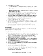
15. Calculate Vc5 (voltage drop in cable #5)
Vc5 = (lc5) (Rc5) = (0.15) (14) = 2.1V
16. Calculate the mx loop card output voltage from the MX-7000
V = V5 + Vc = 20.4 + 2.1 = 22.5 V
17. According to the voltage drop resistor rules stated above: Rd1,Rd2,Rd3 are 0, Rd4=100, and
Rd5=200.
Note that if the voltage at a processor is near the maximum voltage value it is a good idea to
install the next highest voltage dropping resistor value if the resulting XPO voltage remains above
12 VDC. In this way if an XPO fails open or is removed for service then the loss of the drop it
caused will not result in raising the voltage of this processor above 16 VDC.
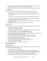
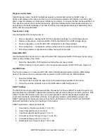
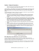
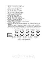
Figure 30 Power distribution plan
MX-7000
loop card
voltage output
22.5 V
node 1
node 2
node 3
node 5
node 4
Dc5 = 1,000 ft.
Ic5 = 150 mA
Vc5 = 2.1 V
Dc1 = 2,000 ft.
Ic1 = 30 mA
Vc1 = 0.84 V
Dc2 = 2,000 ft.
Ic2 = 60 mA
Vc2 = 1.68 V
Dc3 = 2,000 ft.
Ic3 = 90 mA
Vc3 = 2.52 V
Dc4 = 2,000 ft.
Ic4 = 120 mA
Vc4 = 3.36 V
FPS
XPO 1
FPS
XPO 2
FPS
XPO 3
FPS
XPO 5
FPS
XPO 4
V5 = 20.4
Rsd = 200 Ohm
V = 17.04
R d = 1
4
s
00 Ohm
V3 = 14.52
Rsd = 0
V2 = 12.84 V
Rsd = 0
V1 = 12 V
Rsd = 0

