MX-7000 Installation and operation manual
P a g e
| 9
Section 2 Quickstart FPS-2-2M/MPS-4100
Qualified technicians may follow these simplified procedures to install and test an MX-7000 controlled
Fence Protection System, including the installation of the MX-7000 Command and Control Center, the
FPS-2-2M fence protection sensors, and the MPS-4100 microwave protection system. Prerequisites for
using the quick-start procedures are:
•
Attendance at one or more Senstar training courses.
•
Prior MX-7000 field installation experience.
Before proceeding, verify that you have a complete site layout showing zone extents, processor locations,
and conduit interconnections. If you are not familiar with any of the procedures described in this section,
refer to the appropriate manual for more detailed information.
Important installation procedures
Throughout the installation it is very important that the following procedures are observed:
•
Ensure the MX-7000 is connected to a proper electrical ground.
•
Install ground rods and proper grounding at outdoor device locations, all FPS processors, and all
MPS-4100 microwave locations.
•
Use the approved multiconductor shielded cable, or equivalent, for connecting the MX-7000 to
the FPS and MPS units.
(The Senstar Interconnect Cable (p/n SP3922-TUV) is a three-pair, 18 AWG, individually shielded
twisted pair cable, with overall foil shield, braided shield, and high density polyethylene jacket.)
•
The interconnect wiring should be run in conduit, either underground or along the base, or top, of
the fence.
•
Terminate wiring and shields exactly as shown. Improper terminations will cause system noise
and degrade performance.
FPS 2-2 installation
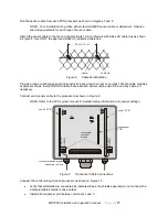
Mount each FPS processor as shown in Figure 7.
•
Use metal brackets or Unistrut-type mounting material to mount the FPS processor(s) on a fence
post.
•
Arrange the conduit/control wiring entrance at the bottom of the enclosure, as shown.
•
Install an approved ground rod at each processor location and connect a minimum 8 AWG ground
wire to the processor bolt as shown.
IMPORTANT: Connect the ground wire directly to the processor bolt as indicated.
NOTE: Consult the local electrical code for information about earth grounding requirements.
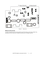
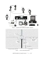
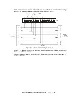
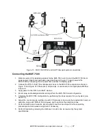
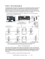
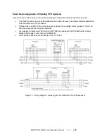
Figure 6 shows the typical copper wire loop interconnection of MX-7000 system components.


