


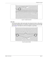


Perimeter layout guidelines
Page 20
FlexZone Product Guide
(1.75 in. to 5 in.). The hardware required for surface-mounting the processor is customer-supplied.
The FlexZone enclosure is hinged and includes a lockable latch (requires a Customer-supplied
pad lock).
Power source and wiring
The FlexZone processor can operate on a wide range of input voltages (12 to 48 VDC). The power
supply, the number of processors, and the lengths of the power cable runs will determine the
gauge of the power cable wiring that is required. In locations where AC power may not be stable or
reliable, an uninterruptable power supply (UPS) should be used for primary power. Assume a
maximum power consumption of 2.5 W per FlexZone processor (with NIC).
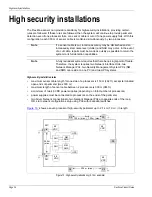
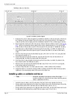
Power over the sensor cables
A group of up to five FlexZone processors can share power via the connected sensor cables. In
this case, the central processor is connected to a 48 VDC power supply. The sensor cables from
the central processor are connected to the two adjacent processors (one on each side). The
processor connected to the power supply requires a stable, low resistance earth ground
connection, which also serves as the ground reference for the connected block of processors.
Power and data distribution is setup via the UCM.
illustrates a 7.2 km (4.5 mi.) 12
processor FlexZone perimeter with power and data over the sensor cables, and redundant Silver
Network communications.
Auxiliary device output power
Processors that are receiving power over the sensor cables can supply up to 2 W of power to an
auxiliary security device through T4, the power connector. The output power is at the same voltage
as the received power input via the sensor cables. The minimum required voltage to enable power
over the sensor cables is 38 VDC.
illustrates connection diagrams of a FlexZone
processor supplying power and carrying alarm data for an UltraWave microwave sensor in both
Local and Remote control modes.
Figure 12: Power and data distribution via sensor cables
48
VDC
48
VDC
48
VDC
NIU
SMS
FlexZone processor
NIC
comm channel
splice/termination
cable side
sensor cable with power & data
network wiring
48 VDC power block
sync master
48 VDC power supply
processor network address
sensor cable
Содержание FlexZone
Страница 66: ...Installing the FlexZone processor Page 66 FlexZone Product Guide ...
Страница 96: ...Page 96 FlexZone Product Guide ...
Страница 102: ...Page 102 FlexZone Product Guide ...


