Manual
Unit
4. Populate the IC-socket on the SLMB with the required alarm- (R
a
) and fault- (R
f
) resistors.
5. KL2 and KL4 are now used as a common alarm- and fault-output (terminals 3 and 5 to 8 may not
be used).
6. Power up the SCU800.
R
a
R
f
SLMB
R
s
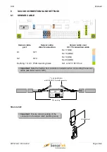
6.2.4 EXTERNAL RESET
External reset input from superordinate equipment.
Input type is selected with BR2:
Contact with external voltage 10 - 30 V DC (default setting)
Contact using internal voltage
EXR+
EXR+
KL9
KL9
10 - 30 V DC
0 V
EXR–
EXR–
KL10
KL10
Terminal designation
Terminal
EXR
+
KL9
–
KL10
Warning:
Do not use an external power supply, if internal power
is selected.
Page 32/44
LISTEC GmbH
60T023-04 / 30.04.2014
BR2
6
5
4
3
2
1
BR2
6
5
4
3
2
1
KL8 KL7 KL6 KL5
KL4
KL3
KL2
KL1
C B
AL2
C A
AL1
C
NO
NC
ST5
C NO NC
FAULT
C A
AL1
C B
AL2
-
+
EXR
-
+
COM
GND
-
+
COM
GND
GND DQ
K1
GND DQ
K2
KL1
KL2
KL3
KL4
KL5
KL6
KL7
KL8
KL9
KL10
KL11
KL12
KL13
KL14
KL15
KL16
KL17
KL18
KL19
KL20
ST1
LG2
8
1
4
5
7
1
14
8
LG1
1
ST7
+
1
ST3
IC1
4
3
1
6
6
1
3
4
FAULT


