


ELECTRICAL CONNECTIONS
Power supply and Modbus interface are available using the Seneca DIN rail bus, via the IDC10 rear connector, or
the Z-PC-DINAL-17.5 accessory.
RS485 GND
RS485 A
RS485 B
Power Supply AC / +
Power Supply AC / -
IDC 10
1
Back connector (IDC 10)
The illustration shows the meanings of the various
IDC10 connector pins if signals are to be sent via
them directly.
Power Supply AC
Ground
Power Supply AC
GNDSHLDG
ND
CANL
/ B
CANL
/
A
DIP SWITCH
Z-PC-DINAL2-17.5 accessory use
If the Z-PC-DINAL2-17.5 accessory is used, signals
can be sent via terminal boards. The illustration
shows the meaning of the various terminals and DIP-
switch position (found in all supports for the DIN rail
listed in Accessories) for the termination of the CAN
network (not used for the Modbus network).
GNDSHLD:
Connection cable signal protection shield (recom
-
mended).
7/8
2
3
-
Vac/Vdc
+ Vac/Vdc
1
Power supply
Terminals 2 and 3 can be used to provide the module with power supply as an al-
ternative to the connection using the Z-PC-DINx bus.
The upper limits must not
be exceeded as this can seriously damage the module
. If the power supply
source is not protected against overload, a safety fuse with a 2.5 max permissible
value must be installed in the power supply line. A.
GND
B
A
4
5
6
ModBus RS485
Connection for RS485 communication using the MODBUS master system as an
alternative to the Z-PC-DINx bus.
N.B. The indication of the RS485 connection polarity is not standardised and in
some devices may be inverted.
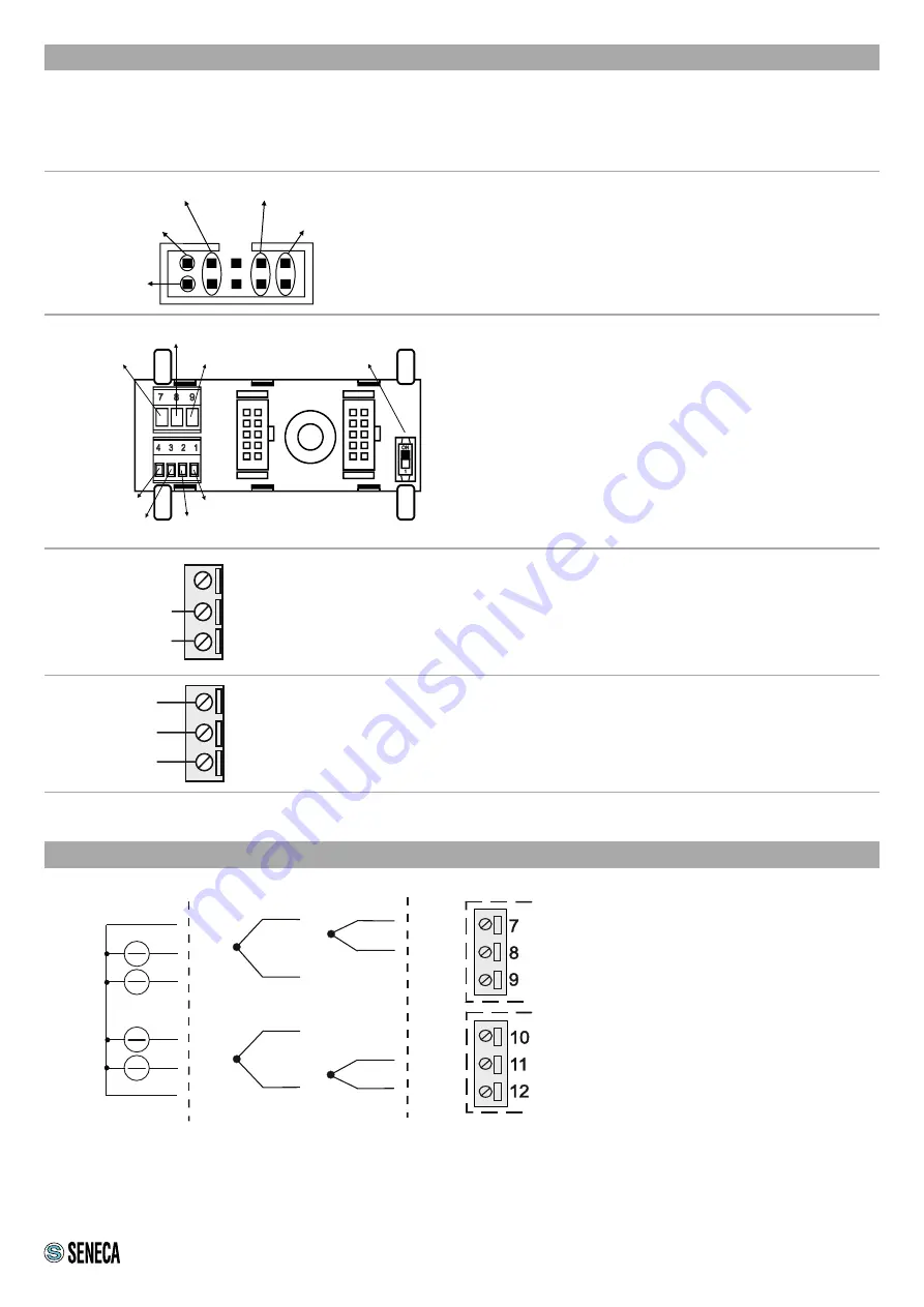
INPUTS
The ground that is available at terminals 7
and 12 is internally connected to all 4 ana-
logue inputs
(mV
)
+
+
+
+
+
+
TC 2
TC 3
+
+
TC 1
TC 4
#I 2
n
#I 1
n
gnd
#I 4
n
#I 3
n
gnd
Note:
To avoid measurement errors caused by external interference, the unused thermocouple input channels
should be short-circuited.
Signal generators
Thermocouples


