


72
ProBee-ZE20S Series User Guide Rev.0.1
Range
0 - 1
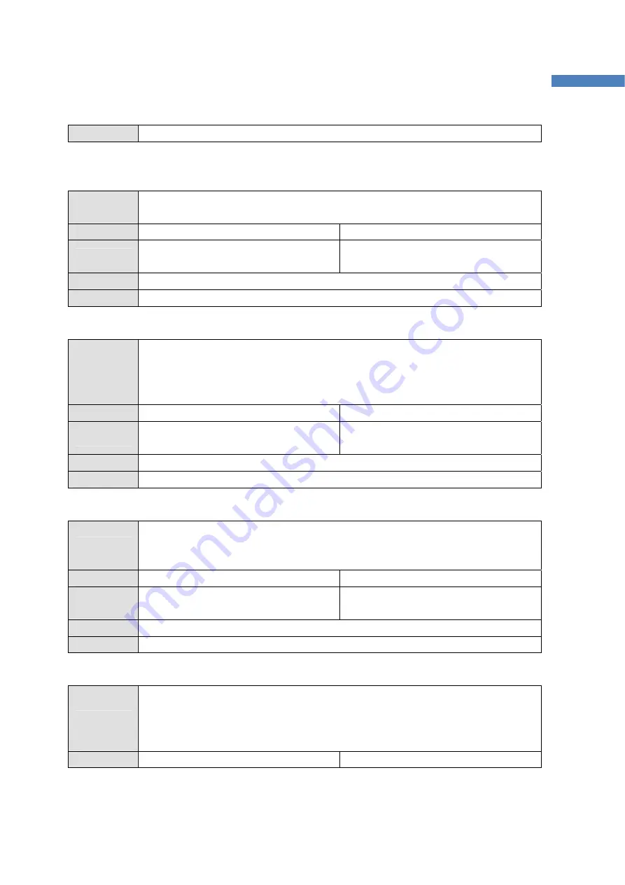
9.4 GPIO
9.4.1 S41
Description
Get/Set the GPIO pull up/down option. If GPIOs are set to DI, it is possible to pull-up or
pull-down with this value. Pull-down = 0, Pull-up = 1.
Execute ATS41?<CR>
ATS41=<value><CR>
Response
<value><CR>
OK<CR>
OK<CR>
Default 0
Range
0 - 1
9.4.2 S42
Description
Get/Set the GPIO monitoring period in seconds. If it is enabled, a node sends GPIO
values to a remote node based on preconfigured destination IEEE address periodically
and it is possible to monitor the GPIO status at the remote node. If set to 0, GPIO
monitoring is disabled.
Execute ATS42?<CR>
ATS42=<value><CR>
Response
<value><CR>
OK<CR>
OK<CR>
Default 0
Range
0 – 10000
9.4.3 S43
Description
Get/Set the GPIO monitoring node. If S43 is 0, the monitoring node is selected by
AT+DESTLA or AT+DL command. If S43 is 1, the sink node is set as the monitoring
node.
Execute ATS43?<CR>
ATS43=<value><CR>
Response
<value><CR>
OK<CR>
OK<CR>
Default 0
Range
0 – 10000
9.4.4 S44
Description
Get/Set the GPIO change detection sampling mode. If it is enabled, a node sends
GPIO values to a remote node based on preconfigured destination IEEE address
immediately when the status of GPIO changes. If set to 0, GPIO monitoring is
disabled.
Execute ATS44?<CR>
ATS44=<value><CR>
Содержание ProBee-ZE20S Series
Страница 76: ...76 ProBee ZE20S Series User Guide Rev 0 1 10 Pin Assignments Figure 10 1 Pin Assignments...
Страница 78: ...78 ProBee ZE20S Series User Guide Rev 0 1 11 Mechanical Drawings Figure 11 1 ZE20SDU Mechanical Drawings...
Страница 79: ...79 ProBee ZE20S Series User Guide Rev 0 1 Figure 11 2 ZE20SDC Mechanical Drawings...
Страница 80: ...80 ProBee ZE20S Series User Guide Rev 0 1 Figure 11 3 ZE20SDS Mechanical Drawings...
Страница 81: ...81 ProBee ZE20S Series User Guide Rev 0 1 Figure 11 4 ZE20SSU Mechanical Drawings...
Страница 82: ...82 ProBee ZE20S Series User Guide Rev 0 1 Figure 11 5 ZE20SSC Mechanical Drawings...


