31
Cause
Grease, varnish, rust or dirt on the filler material.
Solution
Always use quality materials and products.
Keep the filler material always in perfect condi-
tions.
Cause
Incorrect welding mode.
Solution
Carry out the correct sequence of operations for
the type of joint to be welded.
Cause
Pieces to be welded have different characteristics.
Solution
Carry out buttering before welding.
Cold cracks
Cause
Humidity in the weld material.
Solution
Always use quality materials and products.
Keep the weld material always in perfect conditions.
Cause
Particular geometry of the joint to be welded.
Solution
Pre-heat the pieces to be welded.
Carry out post-heating.
Carry out the correct sequence of operations for
the type of joint to be welded.
For any doubts and/or problems do not hesitate to contact
your nearest customer service centre.
6 CONTINUOUS WIRE WELDING THEORY
6.1 Introduction
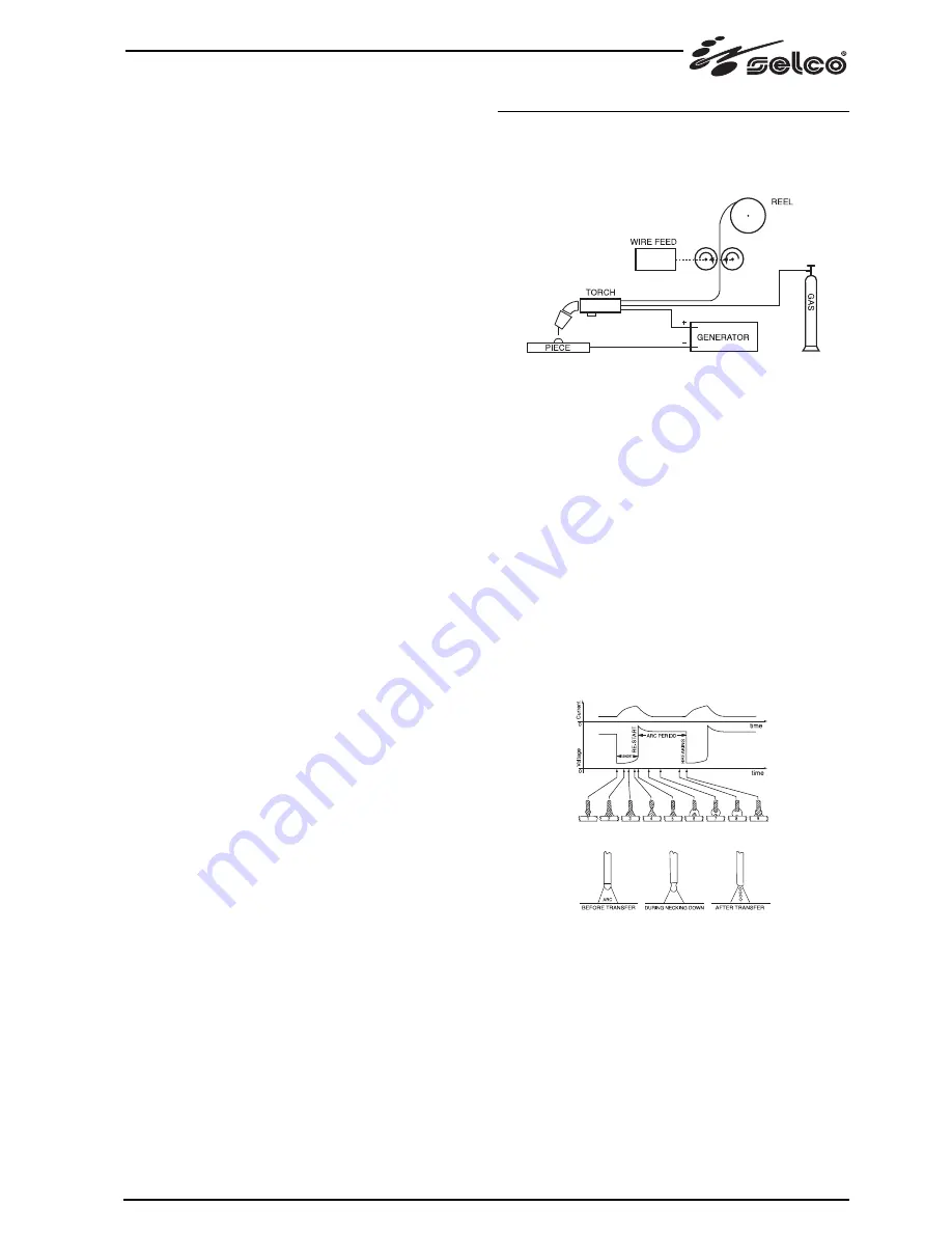
A MIG system consists of a direct current power source, wire
feeder, wire spool, torch and gas.
MIG manual welding system
The current is transferred to the arc through the fusible elec-
trode (wire connected to positive pole); in this procedure the
melted metal is transferred onto the workpiece through the arc
stream. The automatic feeding of the continuous filler material
electrode (wire) is necessary to refill the wire that has melted
during welding.
6.1.1 Methods
In MIG welding, two mains metal transfer mechanism are
present and they can be classified basing on the means by
which metal is transferred from the electrode to the workpiece.
The first one, defined “SHORT-ARC”, produces a small, fast-
freezing weld pool where metal is transferred from the electrode
to the workpiece only during a period when the electrode is
in contact with the weld pool. In this timeframe, the electrode
comes into direct contact with the weld pool generating a short
circuit that melts the wire which is therefore interrupted. The
arc then turn on again and the cycle is repeated (Fig. 1a).
SHORT cycle (a) and SPRAY ARC welding (b)
Another mechanism for metal transfer is called “SPRAY-ARC”
method, where the metal transfer occurs in the form of very
small drops that are formed and detached form the tip of the
wire and transferred to the weld pool through the arc stream
(Fig. 1b).
Fig. 1a
Fig. 1b
Содержание Neomig 3500
Страница 181: ...1 1 1 10 C 40 C 14 F 104 F 25 C 55 C 13 F 131 F 50 40 C 40 00 C 90 20 C 68 F 2000 6500 1 2 10 MIG MAG 181...
Страница 182: ...182 1 3 1 4 11 35 1 5...
Страница 183: ...183 1 6 1 7 EN IEC 60974 10 B A A EN60974 10 A pace maker Zmax Ssc Point of Commom Coupling PCC...
Страница 184: ...1 8 IP S IP21S 12 5 mm 2 2 1 A B 90 B 2 2 10 2 3 400V 230V 184...
Страница 185: ...185 15 Vnom 400V 320V 440V 400V 15 2 1 5 2 4 MIG MAG MIG 1 5 6 2 2 3 4 10 15...
Страница 186: ...186 3 3 1 NEOMIG MIG MAG 3 2 1 2 3 4 3 0 0 5 10 6 7 7 MIG MIG 8 2 4 4 pre gas 9 MIG MIG MIG MIG MIG MIG 10 mm...
Страница 189: ...189 4 5...
Страница 190: ...190 Reset encoder...
Страница 191: ...191...
Страница 192: ...192 6 6 1 MIG 6 1 1 SHORT ARC 1a SHORT a SPRAY ARC b SPRAY ARC 1b 6 1 2 2 3 2 3 1a 1b...
Страница 198: ...198 NEOMIG 4500...
Страница 202: ...202 51 06 028 NEOMIG 4500...
Страница 206: ...206...


