


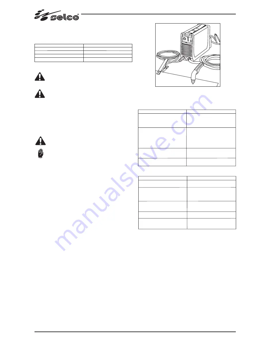
Fig. 3
6.0 PROBLEMS - CAUSES
6.1 POSSIBLE CUTTING DEFECTS
*
: Fuses with a 20A rating are required to make maximum use of the potential of the power
source.
The electrical system must be made by skilled technicians
with the specific professional and technical qualifications
and in compliance with the regulations in force in the
country where the equipment is installed.
The welding power source supply cable is provided with a
yellow/green wire that must ALWAYS be earthed. This yel-
low/green wire must NEVER be used with other voltage
conductors.
* Verity the existence of the earthing in the used plant and the good
condition of the socket/s
* lnstall only plugs that are homologated according to the safety re-
gulations.
5.3 CONNECTING THE EQUIPMENT COMPONENTS
Keep to the safety regulations contalned in section 1.0
WARNINGS-PRECAUTIONS-GENERAL ADVICE.
Connect the componente carefully, in order to avoid po-
wer losses.
5.4 SETTING UP
To set up the plant, follow these instructions:
1.
Place the generator in a dry, clean place with suitable ventilation.
2.
Connect up the compressed air supply with a 1/4 inch to the air inlet
P1 in the filter unit F (Fig.2). The pressure must ensure at least 5 bars
with a flow rate of at least 100 litres a minute.
3.
Position the earthing clamp onto the piece to be cut, ensuring that it
makes a good electric connection (Fig. 3).
4.
Check that all the components of the torch are present and correctly
fitted.
5.
Switch on the system, ensuring the LED's are working correctly.
If torch components are missing or have been assembled incorrectly,
or the compressed air pressure is too low, or entirely lacking, leds L3
and L4 in figure 1 come on respectively to display the fault. The ge-
nerator is shut down until the fault is put right. Press the gas test
pushbutton (T1 in Fig 1) in order to remove residual impurities from
the compressed air circuit, then lift and turn the knob to adjust the
pressure (F1 Fig.2) until the manometer M1 shows a pressure reading
of about 5 bars (carry out the operation keeping the gas test button
pressed down, so as to make the adjustment with air circulating in the
piping).
6.
Set the value of the cutting current with the potentiometer, keeping in
mind the thickness to be dealt with.
7.
Press for a moment the torch button so as to generate the pilot arc;
release the control, checking the machine is correctly operating with
the display panel.It is advisable not to keep the arc lit to no purpose
without making contact, so as to prevent wear on the electrode and
the nozzle. If you continue to use it like this the apparatus itself will
turn off the pilot light after about 6 seconds.
In the case where a fault is found during the above phases, check the
display LED's, and if necessary consult the chapter "Possible electrical
faults" in the manual.
17
5.2 ELECTRIC CONNECTION TO THE SUPPLY MAINS
The equipment is provided with a single electric connection with a 2m
cable positioned in the rear part of the power source.
Size table of the power source input cables and fuses:
Power source
Rated voltage
Voltage range
Delayed fuses*
Power supply cable
GENESIS 30
230 V ±15%
195.5 - 264.5 V
16 A 250 V
3x2.5 mm2
DEFECT
Insufficient penetration
The cutting arc goes out
Substantial burr formation
Nozzle overheating
CAUSE
- Cutting speed too high
- Current set too low
- Earth clamp with inefficient contact
- Thickness of piece excessive
- Electrode, nozzle or diffuser worn
- Air pressure too high
- Cutting speed too low
- Insufficient air flow
- Defective pressure switch
- Supply voltage too low
- Inadequate air pressure
- Cutting speed too low
- Nozzle eroded
- Electrode eroded
- Insufficient air quantity
6.2 POSSIBLE ELECTRICAL FAULTS
DEFECT
Apparatus fails to come on (Yellow LED L1 off)
Pilot arc fails to ignite (with yellow LED L1 on)
Pilot arc fails to ignite (with yellow LED L1
and red LED L3 on)
Fails to transfer from pilot arc to cutting arc
Lack of power output
CAUSE
- Incorrect mains supply
- Break in the contacts of the torch button
(check the connection of the torch attach-
ment is working after having cut off the
power supply)
- Torch parts subject to wear out of action
- Air pressure too high
- Possible problems in control circuits
- Possible problems in control circuits
- Arc sensors faulty (board 15.14.261)
- Protective devices triggered (see chapter on
"Functions of controls")
- Possible problems in control circuits
If you have any doubts or problems, do not hesitate to consult your
nearest Selco technical service centre.
Содержание Genesis 30
Страница 1: ...USE AND MAINTENANCE MANUAL E N G L I S H Genesis 30 POWER SOURCES FOR PLASMA CUTTING...
Страница 2: ......
Страница 12: ...RICAMBI SPARE PARTS ERSATZTEILE PIECES DETACHEES REPUESTOS GENESIS 30 TAV 01...
Страница 14: ...TORCIA PLASMA S30 PLASMA TORCH S30 PLASMA SCHWEI BRENNER S30 TORCHE PLASMA S30 ANTORCHA POR PLASMA S30 TAV 02...


