


15
SHIELDING
The selective shielding of other cables and equipment present in the
surrounding area may reduce the problems due to interference. The
shielding of the entire welding (cutting) installation can be taken in con-
sideration for special applications.
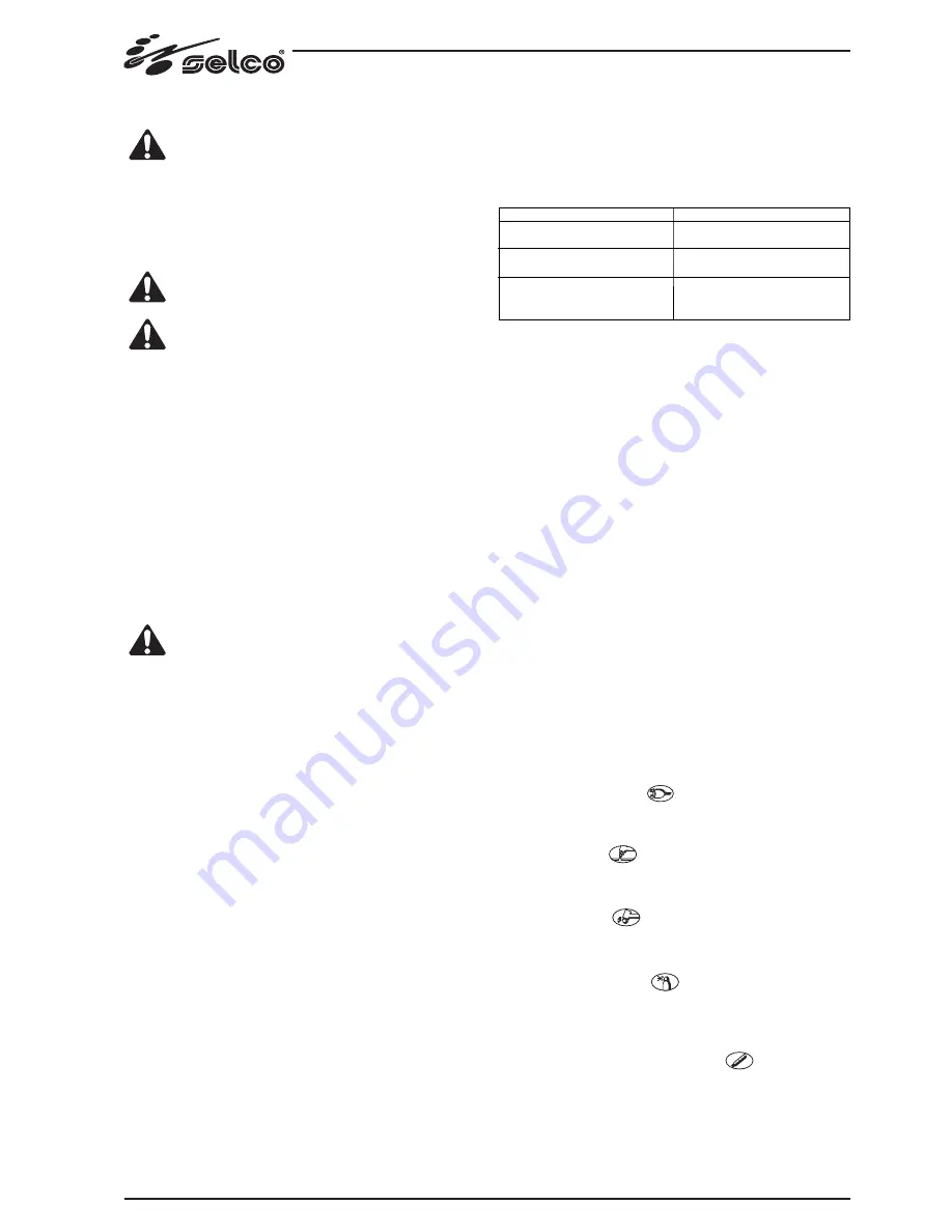
1.3 RISK ANALYSIS
comes from a compressed air canister it must be equipped with a pres-
sure regulator.
A compressed air canister must never be directly coupled
to the machine pressure reducer. Pressure might exceed the
capacity of the reducer which might consequently explode.
1.2 ELECTROMAGNETIC COMPATIBILITY (EMC)
1.2.1 General information
This device is built in compliance with the indications contained in the
harmonized standard EN50199, which the operator must refer to for
the use of this apparatus.
Install and use the apparatus keeping to the instructions
given in this manual.
This device must be used for professional application only,
in industrial environments. It is important to remember
that it may be difficult to ensure the electromagnetic com-
patibility in other environments.
1.2.2 Installation, use and area examination
- The user is responsible for the installation and use of the equipment
according to the manufacturer's instructions.
lf any electromagnetic disturbance is noticed, the user must solve the
problem, if necessary with the manufacturer's technical assistance.
- In any case electromagnetic disturbances must be reduced until
they are not a nuisance any longer.
- Before installing this apparatus, the user must evaluate the potential
electromagnetic problems that may arise in the surrounding area,
considering in particular the health conditions of the persons in the
vicinity, for example of persons with pacemakers or hearing aids.
1.2.3 Emission reduction methods
MAINS POWER SUPPLY
This device must be connected to the supply mains accor-
ding to the manufactures instructions.
In case of interference, it may be necessary to take further precautions
like the filtering of the mains power supply.
lt is also necessary to consider the possibility to shield the power supply
cable.
MAINTENANCE
This device needs routine maintenance according to the manufacturer's
instructions.
When the equipment is working, all the access and operating doors
and covers must be closed and fixed.
This device must not be modified in any way.
WELDING AND CUTTING CABLES
The welding (cutting) cables must be kept as short as possible, positio-
ned near one another and laid at or approximately at ground level.
EQUIPOTENTIAL CONNECTION
The earth connection of all the metal components in the welding (cut-
ting) installation and near it must be taken in consideration.
However, the metal components connected to the workpiece will in-
crease the risk of electric shock for the operator, if he touches said me-
tal components and the electrode at the same time.
Therefore, the operator must be insulated from all the earthed metal
components.
The equipotential connection must be made according to the national
regulations.
EARTHING THE WORKPIECE
When the workpiece is not earthed for electrical safety reasons or due
to its size and position, the earthing of the workpiece may reduce the
emissions. It is important to remember that the earthing of the work-
piece should neither increase the risk of accidents for the operators,
nor damage other electric equipment.
The earthing must be made according to the national regulations.
Risks posed by the machine
Risk of wrong installation.
Electrical risks.
Risks connected with electromagnetic distur-
bances produced by the welding power sour-
ce and induced on the welding power source.
Solutions adopted to pervent them
A manual with the instructions for use has
been produced for this purpose.
Application of the
EN 60974-1
,
EN 50192,
EN 50078
Standards.
Application of the
EN 50199
Standard.
2.0 INTRODUCTION
Genesis 30 is a user-friendly, compact generator for plasma cutting.
Genesis 30 uses compressed air as its only gas source, which can be sup-
plied from a normal compressor or from a suitably sized centralized
plant. It is able to carry out, cheaply, cuts of a high quality up to a thick-
ness of 10 mm in carbon steel, while still keeping its weight and size very
limited.
This optimum performance-to-weight ratio is made possible thanks to
the use, in common with all the Genesis range, of inverter technology.
The current is thus stable, and unaffected by variations in the supply
voltage, in the height of the cutting arc, in the progression speed and
in the thickness of the metal to be cut. The Genesis 30 is equipped
with an automatic circuit for the reignition of the pilot arc, that allows
metal grill structures to be cut in the best way.
There are safety systems that cut off the power circuit when the opera-
tor comes into contact with live parts of the machine, as well as con-
trols to reduce the wear on the electrode and nozzle at the moment
of striking the cutting arc.
The ignition of the pilot arc takes place without the use of high fre-
quency, with an increase in the working life of the parts of the torch
subject to wear, and reduction in the mains interference.
The generator is equipped with:
- a torch, an earth (+) socket,
- front panel,
- rear control panel.
2.1 CONTROLS
2.1.1 Front control panel FP120 (Fig.1)
* L1 : Voltage warning light green led.
Comes on with the start switch (Fig.2) "
I1
" in position "
I
" and indica-
tes that the plant is on and there is voltage.
* Power output light red led.
Comes on as soon as the cutting process starts, and goes off as soon as
it is finished.
* L3: torch cap alarm red led.
Means that the torch cap has not been properly tightened. The gene-
rator has no power output.
* L4: compressed air alarm red led.
Means that the pressure of compressed air is below 3.5 bar, too low
for proper functioning.
The generator has no power output.
* L5: Thermal safety device warning light yellow led.
lndicates that the safety devices like thermal cutout.
With "
L5
" on, the power source remains connected to the supply
mains, but does not supply output power. "
L5
" remains on until the
fault has been removed and in any case until the inner temperatu-
res are not within the normal values; in this case it is necessary to
Содержание Genesis 30
Страница 1: ...USE AND MAINTENANCE MANUAL E N G L I S H Genesis 30 POWER SOURCES FOR PLASMA CUTTING...
Страница 2: ......
Страница 12: ...RICAMBI SPARE PARTS ERSATZTEILE PIECES DETACHEES REPUESTOS GENESIS 30 TAV 01...
Страница 14: ...TORCIA PLASMA S30 PLASMA TORCH S30 PLASMA SCHWEI BRENNER S30 TORCHE PLASMA S30 ANTORCHA POR PLASMA S30 TAV 02...


