background image

TB XRI1-IE   11.01 E

13

5.1.1


Indication of measuring values
and fault data

Indication in faultless condition

In normal operation the display always shows |SEG.
After pressing the push button <SELECT/RESET> the
display switches cyclically to the next measuring value.
After the measuring values had been indicated the set-
ting parameters are displayed. Hereby the LEDs in the
upper section signalize which measured value is indi-
cated, the LEDs in the lower section signalize which
setting parameter is indicated on the display. Longer
actuating the push button resets the relay and the dis-
play changes into normal operation (|SEG).

Indication after pickup / tripping

All of the faults detected by the relay are indicated on
the front plate optically. Here not only the faults are
indicated but also the faulty phase(s) and the protec-
tion function in operation. At pickup the LEDs are flash-
ing, after tripping this changes to continuous light.
In tripped condition "TRIP" appears on the display and
the LEDs of the operating measuring data light up red
together with the LEDs of the tripping parameter. All
operating data, which were measured at the moment
of tripping, can now be called one after another by
pressing push button <SELECT/RESET>. If in this condi-
tion setting parameters are to be indicated, push but-
ton <ENTER> has to be pressed.

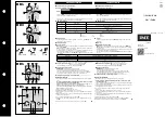
The graphic below shows again the difference be-
tween the different display modes.

<SELECT>

<SELECT>

<SELECT>

<ENTER>

|SEG

TRIP

<SELECT>

<SELECT>

<ENTER>

<SELECT>

Display after tripping

Display in normal operation

Tripping

<RESET>

Measuring data

Parameter

Parameter

Failure data

Figure 5.2: Switching over of the display in dependence of the operating mode

Содержание XRI1-IE

Страница 1: ...XRI1 IE Combined time overcurrent and earth current relay...

Страница 2: ...Trip delay for high set element tI 6 1 7 Pickup current for earth fault element IE 6 1 8 WARN TRIP changeover 6 1 9 Time current characteristics for earth fault element CHAR IE 6 1 10 Trip delay or t...

Страница 3: ...overcurrent protection 8 3 2 Earth fault protection 8 3 3 Switch failure protection 8 3 4 Interface parameter 8 3 5 Inverse time overcurrent protection relay 8 4 Inverse time characteristics 8 5 Outpu...

Страница 4: ...ctable protective functions between definite time overcurrent relay and inverse time overcurrent relay Selectable inverse time characteristics according to BS 142 and IEC 255 4 Normal Inverse type A V...

Страница 5: ...l be blocked if an auxiliary voltage is connected to terminals C1 C1L or C1 C1H See chapter 6 1 20 3 1 3 External reset input By applying the aux voltage C2 C2L or C2 C2H indication and output relays...

Страница 6: ...values can be achieved by HTL PL Soft4 which will be provided on request to gether with the relay The XRI1 IE can be connected to other units of PROFESSIONAL LINE via interface If there is more than...

Страница 7: ...ront plate XRI1 IE 3 2 2 LEDs The LEDs left from the display L1 L2 L3 E are par tially bi colored the green indicating measuring and the red fault indication The LED marked with letters RS lights up d...

Страница 8: ...ECT RESET Switch over LED flash No LED flash FLSH NOFL SELECT RESET Blocking of function EXIT until max setting value LED of blocked parameter Slave address of serial interface 1 32 SELECT RESET RS Ba...

Страница 9: ...ng Warn trip CHAR IE Tripping characteristic for earth fault overcurrent element DEFT NINV VINV EINV tIE Trip delay factor for earth fault low set element s DEFT 0 03 260 EXIT INVS 0 05 10 0 EXIT IE C...

Страница 10: ...n is applied to sup press high frequency harmonics and DC components caused by fault induced transients or other system dis turbances The calculated actual current values are compared with the relay s...

Страница 11: ...Current factor related to set value at which the C T is not yet saturated Moreover the current transformers have to be rated according to the maximum expected short circuit cur rent in the network or...

Страница 12: ...ESET This push button is also used for re setting the display by pressing approx 3s Push buttons are used for in decrementing of the parameter indicated on the display They can be pressed step by step...

Страница 13: ...ptically Here not only the faults are indicated but also the faulty phase s and the protec tion function in operation At pickup the LEDs are flash ing after tripping this changes to continuous light I...

Страница 14: ...e fault current is interrupted DIP switch 3 ON All output relays remains activated and must be reset after fault clearence Manually By pressing push button SELECT RESET External By connecting aux volt...

Страница 15: ...wanted to be stored After pressing the ENTER push button again the password will be inquired by means of the message PSW on the display After the password is given correctly which is prompted by messa...

Страница 16: ...unction of the XRI1 IE relays can be set according to requirement When pressing push buttons ENTER and TRIP at the same time the blocking mode is entered see chapter 6 1 20 5 6 Display of software ver...

Страница 17: ...sent time delay setting value is shown on the display The new setting value can then be changed by using push buttons If through a new setting another relay characteristic other than the old one has b...

Страница 18: ...e quency as a parameter for correct digital sampling and filtering of the input currents By pressing SELECT the display shows f 50 or f 60 The desired nominal frequency can be ad justed by or and then...

Страница 19: ...on is normally on Output relays 1 4 are nor mally off and can be assigned as alarm or tripping re lays to the current functions which can either be done by using the push buttons on the front plate or...

Страница 20: ...n reference as well as for tele phone queries Relay function Output relays Display Lighted LED 1 2 3 4 indication I alarm X _ 2 _ _ I tI tripping X 1 _ _ _ tI I alarm X _ _ 3 _ I tI tripping X 1 _ _ _...

Страница 21: ...path is adjusted Low set element I The pickup current is determined according to the maximum expected load current For example Current transformer ratio 400 5A Maximum expected load current 300A Over...

Страница 22: ...g to indicate that it is not a current fault LEDs which were blinking during trip conditions element had picked up just briefly flash If the relay is still in trip condition and not yet reset TRIP is...

Страница 23: ...the display shows the second part of the soft ware version of the relay e g 4 01 The software version should be quoted in all correspondence Press ing the TRIP button once more the display shows PSW...

Страница 24: ...cuit of XRI1 IE Figure 7 1 Test circuit For testing relays one or three phase current test de vices are required Figure 7 1 shows an example of a single phase test circuit with adjustable current ener...

Страница 25: ...lso to be used for the other phases 7 4 5 Checking the relay operating time To check the relay operating time a timer must be connected to the trip output relay contact The timer should be started sim...

Страница 26: ...current and voltage transformers with the primary side energized Since the cost and poten tial hazards are very high for such a test primary in jection tests are usually limited to very important prot...

Страница 27: ...IN for 10 s 30 x IN continuously 4 x IN 8 2 Common data Dropout to pickup ratio 97 Returning time 30 ms Time lag error class index E 10 ms Minimum operating time 30 ms Transient overreach at instantan...

Страница 28: ...ection Setting range Step Tolerance IE tIE 0 01 2 0 x IN EXIT 0 03 260 s EXIT definite time 0 05 10 EXIT inverse time 0 001 0 002 0 005 0 01 0 02 0 05 x IN 0 01 0 02 0 05 0 1 0 2 0 5 1 0 2 0 5 0 10 20...

Страница 29: ...tection relay According to IEC 255 4 or BS 142 Normal Inverse type A s I t 1 02 0 Is I 14 0 t Very Inverse type B s I t 1 Is I 5 13 t Extremely Inverse type C t I Is t I s 80 2 1 Where t tripping time...

Страница 30: ...7 8 910 20 I IS 0 01 0 1 1 10 100 1000 t s tI 10 0 8 0 6 0 4 0 3 0 2 0 0 05 0 1 0 2 0 3 0 4 0 5 0 6 0 8 1 0 1 4 Figure 8 2 Extremely Inverse type C 1 2 3 4 5 6 7 8 910 20 I IS 0 1 1 10 100 1000 t s t...

Страница 31: ...span 30 x 10 6 operating cycles electrical life span 2 x 10 5 operating cycles at 220 V AC 6 A Contact material silver cadmium oxide AgCdO 8 6 Power supply Auxiliary voltage 16 360 V DC 16 270 V AC P...

Страница 32: ...IEC 255 5 5 kV 1 2 50 s 0 5 J High frequency interference test voltage inputs and outputs between themselves and to the relay frame as per EN 60255 6 IEC 255 6 2 5 kV 1 MHz Electrical discharge ESD te...

Страница 33: ...thout notice 8 9 Relay case Relay XRI1 IE is designed to be fastened onto a DIN rail acc to DIN EN 50022 the same as all units of the PROFESSIONAL LINE The front plate of the relay is protected with a...

Страница 34: ...TB XRI1 IE 11 01 E 9 Order form Time overcurrent relay XRI1 I E 3 phase measuring I I Rated current 1 A 5 A 1 5 Earth current measuring Rated current 1 A 5 A 1 5 RS485 Adjustable with Modbus protocol...

Страница 35: ...current high set element x IN 1 00 tI Trip delay for overcurrent high set element s 0 03 IE Pickup value for earth fault low set element x IN 0 01 WARN TRIP Warning tripping setting TRIP CHAR IE Tripp...

Страница 36: ...of the output relays Function Relay 1 Relay 2 Relay 3 Relay 4 Default setting Actual setting Default setting Actual setting Default setting Actual setting Default setting Actual setting I alarm X I t...

Отзывы: