CW-H COOLER PLC OWNER’S MANUAL 859731-D
|
7
ILL3669-A
CONNECTING
C
mm
2
mm
2
AWG
AWG
7
7
0.28
0.28
mm
mm
0.2...2.5
24...14
24...14
22...14
0.5...0.6
4.42...5.31
22...14
2x 24...18 2x 24...16
2x 22...18 2x 20...16
0.2...2.5
0.25...2.5
0.25...2.5
2x 0.2...1 2x 0.2...1.5
2x 0.25...1 2x 0.5...1.5
in.
in.
N/m
Ø3.5mm (0.14in)
lb/in
COMMUNICATION CABLE SPECIFICATION
•
Suitable for RS 485 applications
•
Minimum 1 twisted pair (TP) and a third conductor
• Copper Conductors
•
0.5 mm
2
/ AWG 20
•
Braided Shield with Drain Wire
•
Characteristic impedance 120Ω
•
Nominal capacity between conductors 89 pF/m
•
Nominal capacity between conductors and shielding 161 pF/m
Use the twisted pair for the ‘+’ and ‘-‘ signal terminals. Use the 3rd conductor for the GND
terminals. Attach the braided shield / drain wire to an EARTH point at one end only.
ILL3705-A
ILL3705-A
WIRING REQUIREMENTS
•
Communication wiring must be kept separate from AC power wiring.
•
Always route communication cables at least 300mm (12”) away from high voltage cables and
high-power machines.
•
Crossover high power cables at right angles.
•
Maximum cable length to first CW-H cooler is 100m.
•
Maximum cable length between each CW-H is 100m.
Note: Non-shielded cables are not protected against electromagnet interference which can cause
signal degradation.
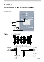
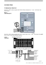
Attach the 120Ω resistor (supplied with Wall Controller) between the "+" and "-" terminals of
the Wall Controller
Attach the 120Ω resistor (supplied with CW-H cooler) between the "+" and "-" terminals of
the last CW-H cooler on the RS 485 Modbus network.
Do not fit the 120Ω resistor supplied with the remaining CW-H cooler installed between the Wall
Controller and the last CW-H coolers.
See Annex A for example wiring schematics
Содержание CW-H 2020 PLC
Страница 1: ...OWNER S MANUAL CW H 2020 PLC WALL CONTROLLER English Original English Instructions ILL2468 A ...
Страница 2: ......
Страница 30: ...28 859731 D ...
Страница 31: ......

