background image

    CW-H COOLER PLC OWNER’S MANUAL 859731-D  

|  

21


DEVICE

ILL3650-B

DEVICE NUMBER

DEVICE INFORMATION

CW-H15S PLUS

DEVICE TYPE

PRESS TO CYCLE 

THROUGH ALL 

DEVICES
DEVICE MESSAGE 

BAR

SETTING SCREENS

DEVICE INFORMATION

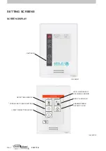
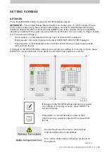
Use the DEVICE screen to access information about individual coolers installed on RS 485 Modbus

network. Press the LEFT and RIGHT buttons to access each node address.

The DEVICE message bar displays messages as follows,

1.  Standby – indicates that the cooler is on but not operating.

2.  Watering In Progress – indicates that the indirect circulation pump is ON and water is being 

pumped to the cores.

3.  Core Drain In Progress – indicates that the indirect circulation pump is OFF and that the 

system is waiting for the water to drain back to the tank.

4.  Tank Fill In Progress – indicates that the water level in the tank is below the low probe and the 

inlet solenoid valve is ON to fill the tank.

The fault message bar at the bottom will display any active faults. If multiple active faults are 

present, the message will cycle through each in turn.

Use the FAULT RESET button to clear all active faults.

ILL3650-B

ILL3650-B

DEVICE NUMBER

DEVICE INFORMATION

CW-H15S PLUS

DEVICE TYPE

PRESS TO CYCLE 

THROUGH ALL 

DEVICES
DEVICE MESSAGE 

BAR

DEVICE NUMBER

DEVICE TYPE

PRESS 

TO CYCLE 

THROUGH 

ALL DEVICES
DEVICE 

MESSAGE 

BAR

Содержание CW-H 2020 PLC

Страница 1: ...OWNER S MANUAL CW H 2020 PLC WALL CONTROLLER English Original English Instructions ILL2468 A ...

Страница 2: ......

Страница 3: ...G Communication Cable Specification 7 Wiring Requirements 7 Power 8 Terminating Resistor 9 OPERATION SCREENS Main Menu 10 Cool Mode Manual Speed Control 11 Cool Mode Automatic Speed Control 12 Vent Mode 13 Program Mode 14 Edit The 7 Day Program 15 SETTING SCREENS Screen Display 16 Time And Date 17 Language 17 Security Lock 18 Configuration 18 Network 19 Auto Restart 20 Room Sensor 20 Ambient Senso...

Страница 4: ...idity non condensing 0 to 75 Embedded Temperature Sensor Characteristics Type 10 k NTC type 2 thermistor Resolution 0 1 o C 0 2 o F Measurement range 40 to 50 o C 40 to 122 o F Accuracy 0 5 o C 0 9 o F at 21 o C 70 o F typical calibration Embedded Humidity Sensors Characteristics Type and calibration Single point calibrated bulk polymer Precision Reading range from 10 to 90 R H non condensing 10 t...

Страница 5: ...ENSOR G TO WALL CONTROLLER TO NEXT COOLER TO ROOM SENSOR OPTIONAL KIT 120 OHM MODBUS TERMINATING RESISTER TO BE FITTED TO LAST COOLER ONLY SENSOR U1 SENSOR U2 SENSOR G0 SENSOR G TO AMBIENT SENSOR OPTIONAL KIT 24Vdc POWER AND RS 485 MODBUS COMMUNICATIONS WIRING 120Ω ILL3630 B RS 485 RS 485 GND ILL3630 B QUICK START WALL CONTROLLER CW H COOLER ILL3631 C ...

Страница 6: ... node address set Refer to installation literature provided with the cooler for setup instructions Enter SETTINGS CONFIGURATION NETWORK menu ILL3633 B List shows all detected coolers Press SAVE to commit detected coolers to Wall Control memory QUICK START ILL3632 A INTERNAL TEMPERATURE HUMIDITY TIME ON OFF COOL MODE VENT MODE PROGRAM MODE SETTINGS DATE DATE TIME ON OFF COOL MODE VENT MODE INTERNAL...

Страница 7: ...xternal walls Avoid mounting the wall control near heat sources such as stoves and televisions Do not locate in the direct airflow of the duct outlets Do not locate in strong drafts or in dead spots such as cupboards drawers Always seal the wall cable entry hole Avoid blocking or restricting the vent holes located on the underside of the Controller as this is where the sensors are located Importan...

Страница 8: ...rill 5 Install anchors NOT INCLUDED in wall 3 6 Insert cable in central hole of base 7 Place rear cover on the wall and align it with mounting holes 4 8 Insert screws NOT INCLUDED in mounting holes on each side of base 5 9 Insert POWER and CONTROL wiring according to wiring chart 10 Gently push excess wiring back into hole 11 Gently align cover to top of base and snap in place from bottom 6 12 Ins...

Страница 9: ...drain wire to an EARTH point at one end only ILL3705 A ILL3705 A WIRING REQUIREMENTS Communication wiring must be kept separate from AC power wiring Always route communication cables at least 300mm 12 away from high voltage cables and high power machines Crossover high power cables at right angles Maximum cable length to first CW H cooler is 100m Maximum cable length between each CW H is 100m Note...

Страница 10: ...ll be un able to control the remaining coolers on the network Use proper wire sizes to meet voltage and current requirements and copper conductors If using a dedicated power supply it must be rated Safety Extra Low Voltage SELV according to IEC 61140 These sources of power are isolated between the electrical input and output circuits of the power supply as well as simple separation from ground ear...

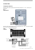
Страница 11: ... CW H cooler on the RS 485 Modbus network ILL3638 B TERMINATING RESISTOR WALL CONTROLLER CW H COOLER ILL3638 B GND ILL3631 C RS 485 RS 485 RS 485 GND W C 24Vdc W C 0Vdc RS 485 RS 485 RS 485 GND SENSOR U1 SENSOR U2 SENSOR G0 SENSOR G TO WALL CONTROLLER TO NEXT COOLER TO ROOM SENSOR OPTIONAL KIT 120 OHM MODBUS TERMINATING RESISTER TO BE FITTED TO LAST COOLER ONLY SENSOR U1 SENSOR U2 SENSOR G0 SENSOR...

Страница 12: ...ENU OPERATION SCREENS ILL3632 B ILL3632 A INTERNAL TEMPERATURE HUMIDITY TIME ON OFF COOL MODE VENT MODE PROGRAM MODE SETTINGS DATE DATE TIME ON OFF COOL MODE VENT MODE INTERNAL TEMPERATURE HUMIDITY PROGRAM MODE SETTINGS ...

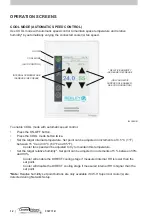
Страница 13: ...ol Press the ON OFF button Press the COOL mode button once Press the INDIRECT and or DIRECT buttons as required to enable the respective cooling stages Press the FAN SPEED UP DOWN arrow buttons to set fan speed Note Relative humidity set point buttons are only available if CW H Supercool cooler s are detected during Network Setup ON OFF COOL MODE MANUAL CONTROL INDIRECT COOLING STAGE ON OFF DIRECT...

Страница 14: ... o C 60 o F and 85 o F Cooler fan speed will be adjusted to try to maintain this temperature Set the target relative humidity Set point can be adjusted in increments of 5 between 50 and 90 Cooler will enable the DIRECT cooling stage if measured internal RH is lower than the set point Cooler will disable the DIRECT cooling stage if measured internal RH is higher than the set point Note Relative hum...

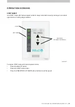
Страница 15: ...rol to keep connected cooler s running at a constant speed with no cooling stage enabled To enable VENT mode with manual speed control Press the ON OFF button Press the VENT mode button Press the FAN SPEED UP DOWN arrow buttons to set fan speed ILL3644 C ILL3644 C ON OFF VENT MODE FAN SPEED INCREASE DECREASE ...

Страница 16: ... required set points via the SETTINGS menu When PROGRAM mode is enabled the wall controller will check the current day time temperature and relative humidity setpoints against the real time current values and run the connected cooler s as required To enable PROGRAM mode Press the ON OFF button Press the PROGRAM mode button The controller will display the current time period Note Relative humidity ...

Страница 17: ...0 Turn OFF set points are ignored 16 00 Turn ON with set points of 24C and 60 RH 22 00 Turn OFF set points are ignored Press the left and right arrow buttons to cycle through each day of the week When finished setting a schedule for a particular day press SAVE DAY Alternatively press SAVE ALL to save the shown schedule to all days Note Relative humidity set point buttons are only available if CW H...

Страница 18: ...P TIME AND DATE WALL CONTROLLER SOFTWARE VERSION CONFIGURE COOLER SETTINGS VIEW CONNECTED DEVICES ENABLE DISABLE SECURITY LOCK SETUP LANGUAGE SETUP TIME AND DATE CONFIGURE COOLER SETTINGS VIEW CONNECTED DEVICES WALL CONTROLLER SOFTWARE VERSION SETUP LANGUAGE ENABLE DISABLE SECURITY LOCK ...

Страница 19: ...n finished press SAVE These values are used in the PROGRAM mode and for time stamping fault codes ILL3648 A ILL3648 A SETTING SCREENS LANGUAGE ILL3827 A ILL3827 A To change the Wall Controller Language press the Change Langauge box and select from ENGLIGH default SPANISH ITALIAN and FRENCH Note The Wall Controller will automatically restart if the language is changed ...

Страница 20: ...user passcode If enabled the Security Lock screen will appear 60 seconds after the screen has been idle Enter the user passcode to remove the Security Lock screen and make changes to the Wall Controller operating mode Press the back button to view the Wall Controller operating mode No changes are allowed Press the Service Button to enter the Seeley Service 7378 passcode Full access is granted If t...

Страница 21: ...the list If changes to the RS 485 Modbus network are required e g adding or removing a cooler press MODIFY to re scan all nodes Press SAVE to commit the new network to memory SETTING SCREENS ILL3830 A Press SAVE to commit detected coolers to Wall Control memory Unused nodes will be removed from the list If changes to the RS 485 Modbus network are required e g adding or removing a cooler press MODI...

Страница 22: ...ity sensors each sold and supplied separately Use the Room Sensor screen to enable additional sensors for use in AUTOMATIC COOL and PROGRAM modes Refer to literature provided with the sensor for installation and setup instructions AMBIENT SENSOR CW H coolers can be used with additional ambient external temperature and relative humidity sensors each sold and supplied separately Use the Ambient Sens...

Страница 23: ...being pumped to the cores 3 Core Drain In Progress indicates that the indirect circulation pump is OFF and that the system is waiting for the water to drain back to the tank 4 Tank Fill In Progress indicates that the water level in the tank is below the low probe and the inlet solenoid valve is ON to fill the tank The fault message bar at the bottom will display any active faults If multiple activ...

Страница 24: ...ous screen Each fault is time stamped based on the settings from the TIME AND DATE screen Press NEXT to cycle through 3 pages of fault history Press CLEAR to remove all historical faults VIEW UP TO 3 PAGES OF HISTORY RETURN TO DEVICE SCREEN CLEAR FAULT HISTORY MONITOR ILL3651 B ILL3651 B The monitor screen displays the status of each of the important components of the cooler ...

Страница 25: ...RE to remove the pop up screen The fault will remain active in the background and the fault code will be added to the FAULT HISTORY screen of the individual cooler Press RESET to remove the pop up screen and restart the effected cooler The fault code will be added to the FAULT HISTORY screen of the individual cooler If the fault re occurs the pop up screen will re appear SETTING SCREENS ...

Страница 26: ...d lock the Wall Controller When applied no device control is possible and connected devices will display REMOTE SHUTDOWN Remove the input signal to resume running in the last known Wall Controller operating mode Refer to Appendix for example wiring schematic Note Connected devices must have software 90R0821 or later installed ILL3832 A ILL3832 A ...

Страница 27: ...agement probe Fault Code 6 FAILURE TO CLEAR HIGH PROBE Water still detected at high probe after 4 hours running in Cool mode Check solenoid valve not stuck open Check all pumps operating when required Clean pumps Check pump hoses not blocked Check excessive rain not entering cooler Clean water management probe Fault Code 7 MOTOR ERROR Check Motor Power Cable connections Check Motor Communications ...

Страница 28: ... The set temperature has been achieved and the coolers are in standby The Controller is in PROGRAM mode and the current time period specifies the cooler is OFF Review the schedule via the SETTINGS PROGRAM screen Check SETTINGS DEVICE FAULT HISTORY Check and rectify Faults Temperature and or Relatively Humidity values are not steady constantly changing Avoid blocking or restricting the vent holes l...

Страница 29: ... APPENDIX EXAMPLE WIRING SCHEMATIC G G 0 U 1 U 2 G G 0 U 1 U 2 120 OHM MODBUS TERMINATING RESISTER FIRST COOLER INTERMEDIATE COOLERS FINAL COOLER WALL CONTROLLER AMBIENT SENSOR OPTIONAL KIT ROOM SENSOR OPTIONAL KIT BMS LOCK BMS ERROR ILL3706 C ...

Страница 30: ...28 859731 D ...

Страница 31: ......

Страница 32: ...y specifications are subject to change without notice Please consult with your dealer to confirm the specifications of the model selected MANUFACTURED BY SEELEY INTERNATIONAL PTY LTD 112 O SULLIVAN BEACH RD LONSDALE SA 5160 AUSTRALIA IMPORTED BY SEELEY INTERNATIONAL EUROPE LTD Unit 11 Byron Business Centre Duke Street Hucknall Nottingham NG15 7HP United Kingdom SEELEY INTERNATIONAL AMERICAS LTD 10...

Отзывы: