Nnn-0000nn
© Copyright 2017 SecureALL Corporation
Page
9
of
18
12.
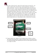
Hold the ends of the wires that are shown in Figure 19 and pull them lightly to tension
the cable while sliding the bottom rail back onto the pushbar unit. Make sure that the
cable remains seated in the channel between the rail and the pushbar unit.
13.
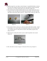
The end of the cable and the Lockdown Switch are now connected using the fasteners
in Figure 20. Place one white wire from both the Switch and the cable into a fastener
and crimp it using a pair of pliers (Figure 21). Repeat for the second set of white wires.
Figure 20 Figure 21
14.
The same procedure is carried out to connect the cable and the battery holder. Connect
the red battery wire to the red cable wire and the black battery wire to the black cable
wire. Install the batteries, being careful to ensure correct polarity (negative at the
spring connection).
15.
Install the first mounting bracket that is used to attach the pushbar unit to the door
(Figure 22).
Figure 22
16.
Place the bracket as shown in Figure 23 and secure with screws per Figure 24.
Содержание SA-PHR
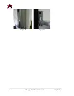
Страница 16: ...Nnn 0000nn Copyright 2017 SecureALL Corporation Page 16 of 18 Figure 43 Figure 44...
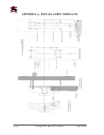
Страница 17: ...Nnn 0000nn Copyright 2017 SecureALL Corporation Page 17 of 18 APPENDIX A INSTALLATION TEMPLATE...
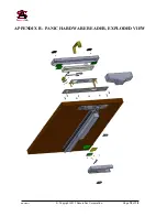
Страница 18: ...Nnn 0000nn Copyright 2017 SecureALL Corporation Page 18 of 18 APPENDIX B PANIC HARDWARE READER EXPLODED VIEW...


